
Apparatus and method for compensating images in display device

a display device and image technology, applied in the field of display devices, can solve the problems of blocking artifacts in decoded images, images compressed at a high compression rate have serious blocking artifacts, and blocking artifacts

Inactive Publication Date: 2006-07-20
LG ELECTRONICS INC
View PDF17 Cites 44 Cited by
  • Summary
  • Abstract
  • Description
  • Claims
  • Application Information

AI Technical Summary

Benefits of technology

[0009] An object of the present invention is to provide an apparatus and method for compensating images in a display device, which removes blocking artifacts from images in real time while retaining edge information in the images.

Problems solved by technology

At more than a certain compression rate, the block-based image coding causes blocking artifacts in the decoded image due to discontinuous luminance of blocks of the image at the boundaries between the blocks.
Images compressed at a high compression rate have serious blocking artifacts, and smooth areas in the images look as if they are composed of blocks of a specific size.
Blocking artifacts reduce the image quality more significantly than a loss of details in the image caused by the compression.
The preprocessing method cannot be applied to coding formats such as JPEG and MPEG whose encoding and decoding procedures have been standardized.
Although it can reduce blocking artifacts in real time, the filtering method has a problem in that it damages edge information of the original image.
However, it is difficult for the transform coding method to reduce blocking artifacts in real time since it requires a great deal of calculation.

Method used


Image

  • Apparatus and method for compensating images in display device
  • Apparatus and method for compensating images in display device
  • Apparatus and method for compensating images in display device

Examples


Embodiment Construction

[0027] Reference will now be made in detail to the preferred embodiments of the present invention, examples of which are illustrated in the accompanying drawings. Wherever possible, the same reference numbers will be used throughout the drawings to refer to the same or like parts.

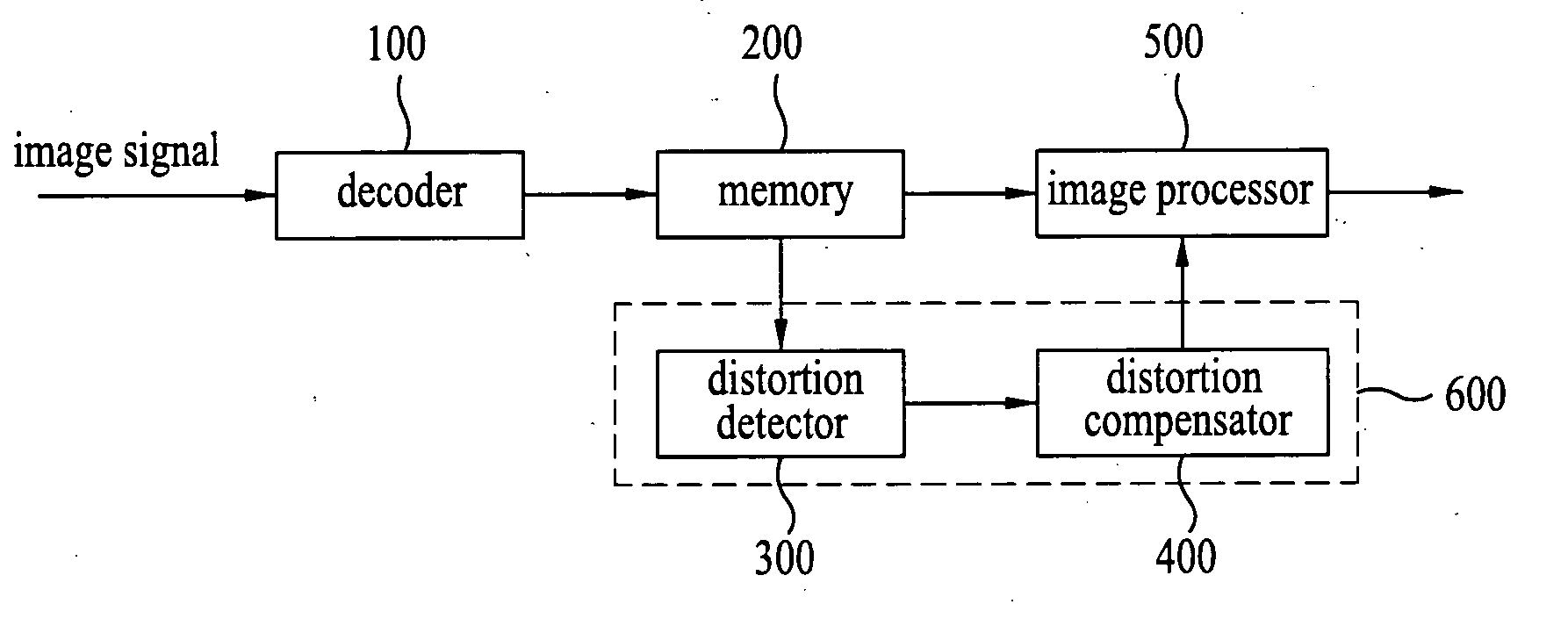
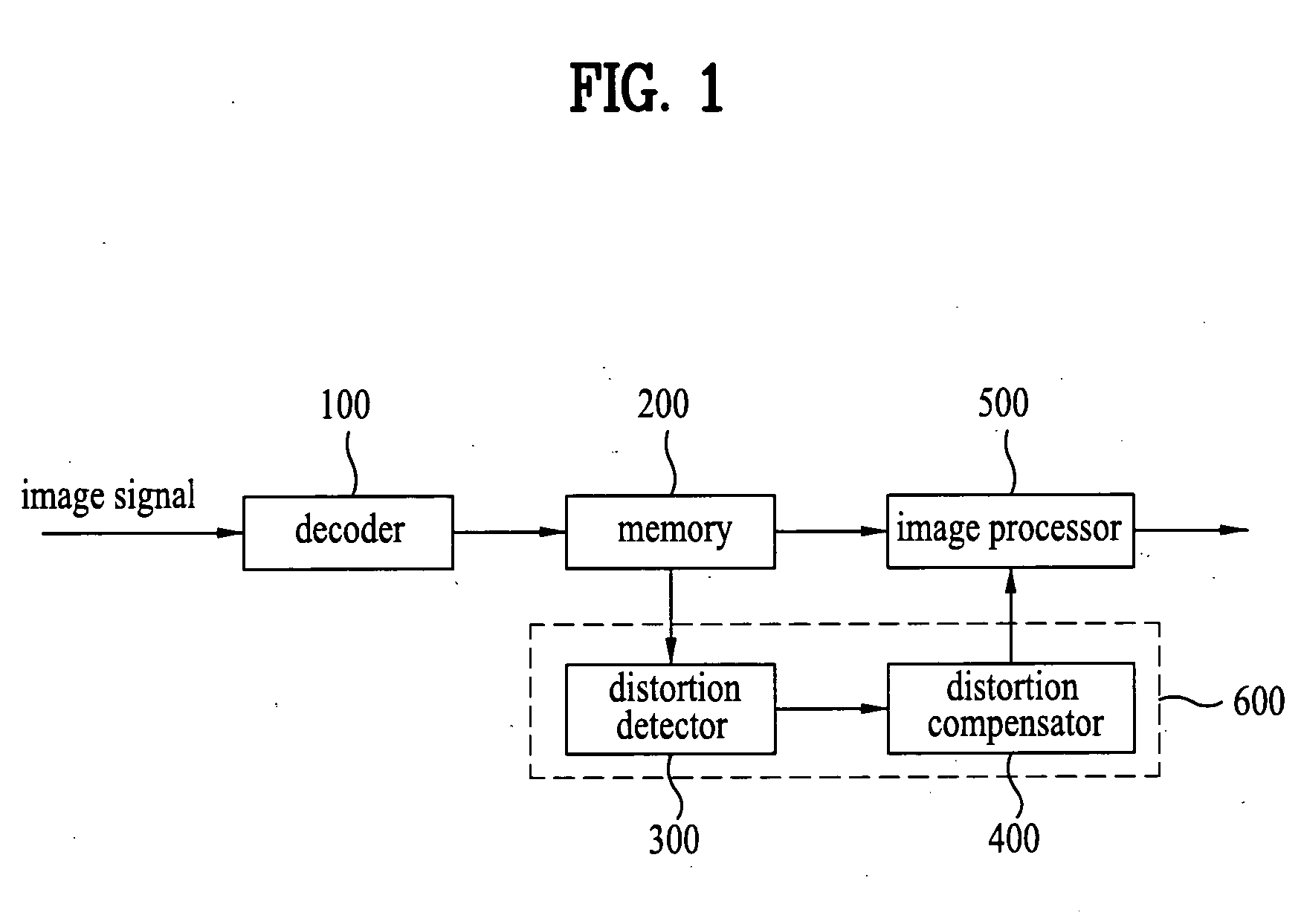
[0028]FIG. 1 is a block diagram of a display device according to the present invention. As shown in FIG. 1, a decoder 100 in the display device receives an image signal transmitted from a broadcasting station or receives an image signal from external devices. For example, the decoder 100 receives a broadcast signal tuned by a tuner or an image signal in compressed format such as JPEG or MPEG. The received image signal is a signal that has been compressed on a per block basis. Each block is composed of 2×2, 4×4, 8×8, or 16×16 pixels. The decoder 100 decodes and transmits the received image signal to a memory 200.

[0029] A controller 600 according to the present invention includes a distortion detector 300 a...


PUM


Abstract

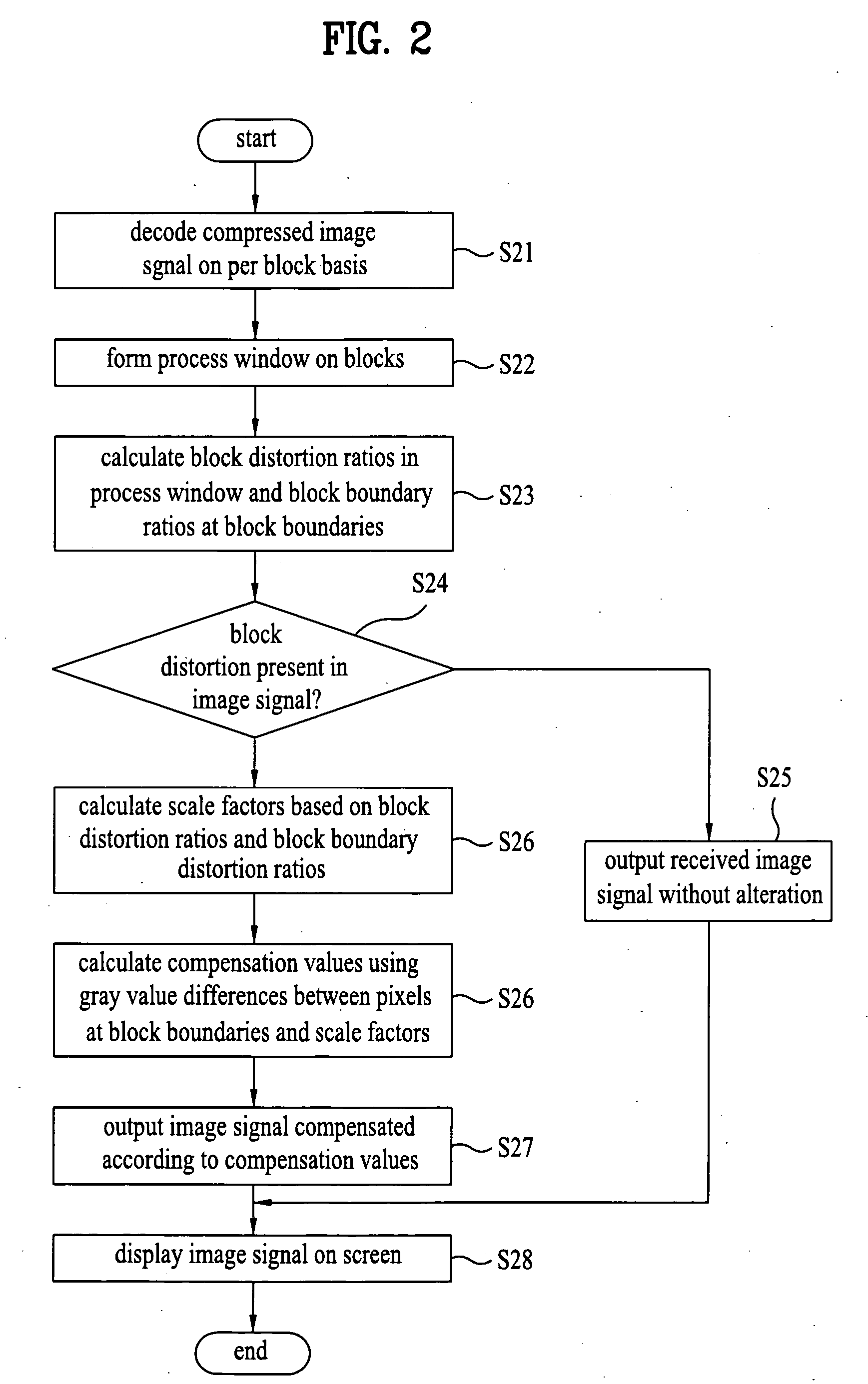
An apparatus and method for compensating images in a display device is disclosed. Distortion ratios of image blocks are calculated based on a gray value difference between each of a plurality of pairs of pixels in the image blocks that face each other at a boundary between the image blocks. Compensation parameters are set based on the calculated block distortion ratios. Distortion compensation values of the image blocks are calculated based on the gray value difference and the set compensation parameters. The image blocks are then compensated according to the calculated distortion compensation values.

Description

[0001] This application claims the benefit of the Korean Patent Application No. 10-2005-003772, filed on Jan. 14, 2005, which is hereby incorporated by reference as if fully set forth herein. BACKGROUND OF THE INVENTION [0002] 1. Field of the Invention [0003] The present invention relates to a display device, and more particularly, to an apparatus and method for compensating images in a display device to reduce blocking artifacts that appear in the images. [0004] 2. Discussion of the Related Art [0005] A variety of compression techniques have been used to increase image transfer rates and storage efficiencies. Recent transform techniques widely used for image compression include Discrete Cosine Transform (DCT) and wavelet transform. The DCT technique has been used for JPEG, MPEG, and H.26X, and the wavelet transform technique has been used for JPEG2000. [0006] In block-based image coding techniques such as JPEG and MPEG, an image is divided into blocks of a specific size and each bl...

Claims


Application Information

Patent Timeline
IPC IPC(8): G06K9/36G06K9/40
CPCH04N19/61H04N19/60H04N19/117H04N19/86H04N19/182H04N19/80H04N19/14
Inventor BAE, MUN SIKSONG, WOO JIN
Owner LG ELECTRONICS INC
Learn More