Communication apparatus and communication method

a technology applied in the field of communication apparatus and communication method, can solve the problems of reducing transmission efficiency and effective data transmission speed, and achieve the effect of suppressing a decrease in data transmission efficiency, excellent reception quality, and improving reception quality

Active Publication Date: 2006-07-20
PANASONIC INTELLECTUAL PROPERTY CORP OF AMERICA
View PDF6 Cites 27 Cited by
  • Summary
  • Abstract
  • Description
  • Claims
  • Application Information

AI Technical Summary

Benefits of technology

[0014] It is an object of the present invention to provide a communication apparatus and communication method that enable excellent reception quality to be obtained while suppressing a decrease in data transmission efficiency. In order to achieve this object, when a first modulated signal is transmitted from a first antenna and a second modulated signal is transmitted from a first antenna, the signal point arrangement mode of at least one modulated signal of the first modulated signal and second modulated signal is changed in the time direction or the frequency direction.
[0015] By this means, the modulated-signal signal point arrangement changes for each time or each subcarrier, and therefore, on the receiving side, the Euclidian distance between a candidate signal point and reception point is large at a particular time or in a particular subcarrier, and the Euclidian distance between a candidate signal point and reception point is small at a particular time or in a particular subcarrier. As a result, a diversity effect can be obtained, and reception quality can be improved.
[0016] Also, in the present invention, the first modulated signal is formed by modulating the same data of first transmit data a plurality of times while changing the signal point arrangement mode, and the second modulated signal is formed by modulating second transmit data without changing the signal point arrangement mode. By this means, the demodulation result of a first modulated signal obtained based on a received signal of a time or subcarrier of good reception quality can be made a first modulated signal received digital signal, a received digital signal of a second modulated signal received at a time or in a subcarrier of poor reception quality can be obtained from a received signal of that time or subcarrier of poor reception quality using a received digital signal of the first modulated signal of a time or subcarrier of good reception quality already determined, and the error rate performances of the second modulated signal received at a time or in a subcarrier of poor reception quality can also be improved. As a result, a received digital signal with good error rate performances can be obtained for both the first modulated signal and the second modulated signal.
[0017] Moreover, in the present invention, a modulated signal formed from different transmit data is basically transmitted from each antenna, enabling a decrease in data transmission efficiency to be suppressed to a greater extent than when space-time block coding is used.

Problems solved by technology

However, if the precision of separation and demodulation of the modulated signals is poor, the effective data transmission speed will decrease.
However, a drawback with the use of space-time block coding technology is that, while reception quality (error rate performances) certainly improves, transmission efficiency decreases.

Method used


Image

  • Communication apparatus and communication method
  • Communication apparatus and communication method
  • Communication apparatus and communication method

Examples


embodiment 1

(1) EMBODIMENT 1

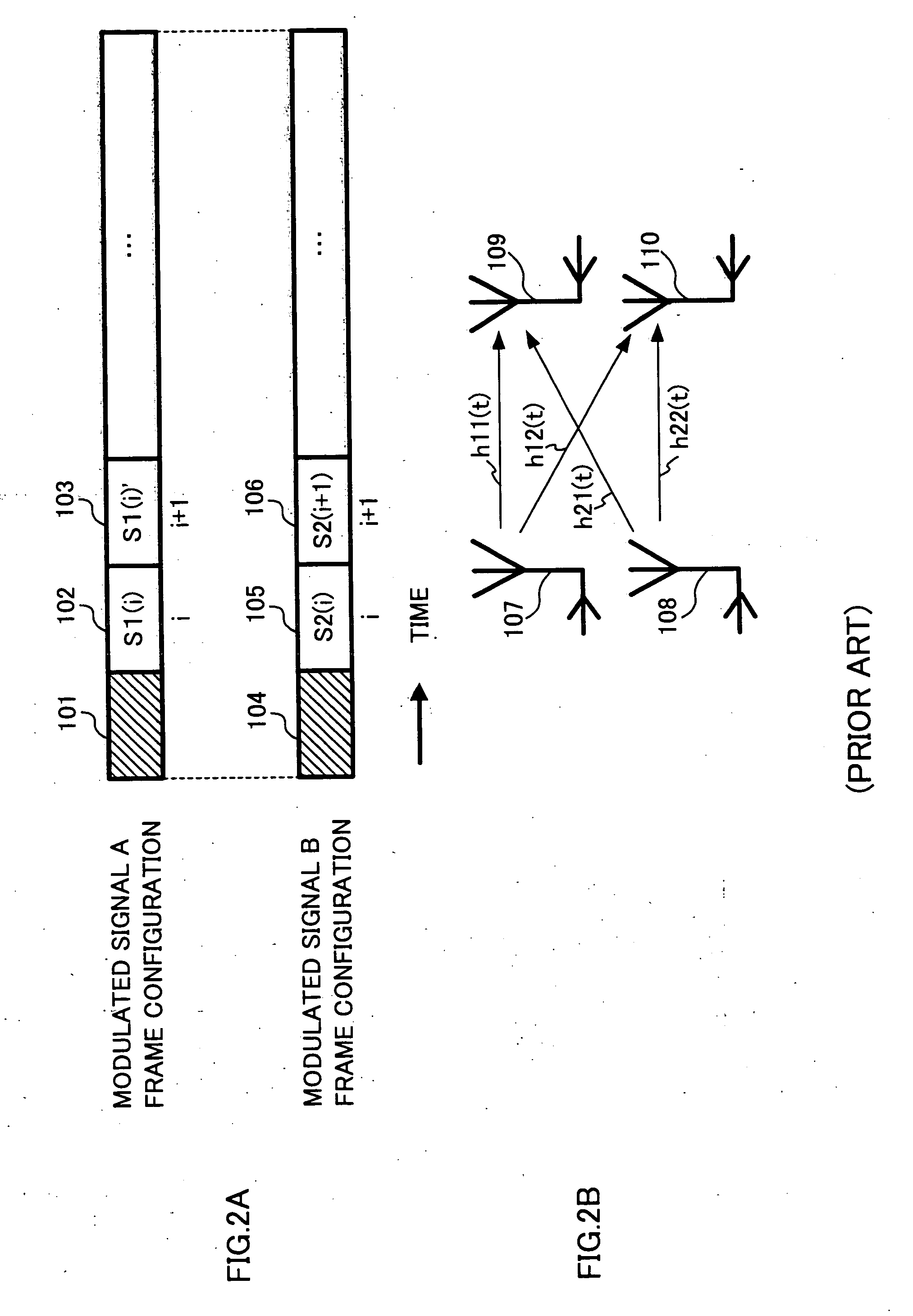
[0080] In this embodiment it is proposed that, when a first and second antenna are used and a different modulated signal is transmitted from each antenna, the same data be transmitted a plurality of times for only one modulated signal. In this embodiment, two modulated signals are formed by modulating two different streams of data, and these two modulated signals are transmitted from different antennas. At this time, in a modulated signal transmitted from one of the antennas, the same data is transmitted a plurality of times, changing the signal point arrangement mode. By this means, since different modulated signals are basically transmitted from each antenna, the error rate performances of data transmitted a plurality of times can be improved, and as a result, the error rate performances of both streams (the two streams) can be improved, while maintaining a higher data transmission speed than when space-time block coding is used.

[0081]FIG. 2A shows frame configura...

embodiment 2

(2) EMBODIMENT 2

[0220] In Embodiment 1, it was proposed that, in transmitting two different modulated signals using two antennas, the same data be transmitted a plurality of times for only one of the modulated signals. In contrast, in this embodiment it is proposed that, in transmitting three different modulated signals using three antennas, the same data be transmitted a plurality of times for one or two of the three modulated signals, and associated actual frame configurations and apparatus configurations are described.

[0221]FIG. 15, in which parts corresponding to those in FIG. 2A are assigned the same codes as in FIG. 2A, shows sample frame configurations of modulated signals according to this embodiment. In this embodiment, a modulated signal C is transmitted at the same time as modulated signal A and modulated signal B. Modulated signal C contains a radio wave propagation environment estimation symbol 1401. Reference codes 1402 and 1403 denote data symbols. Modulated signal C...

example 1

(2-1) VARIANT EXAMPLE 1

[0265] In this embodiment a case has been described in which the frame configurations transmitted by transmitting apparatus 1700 are as shown in FIG. 15, but the transmitted frame configurations may also be as shown in FIG. 16. The difference between the frame configurations in FIG. 16 and the frame configurations in FIG. 15 is that the time difference in transmitting signal S1(i) in which the same data is modulated in modulated signal A is made small in the case of FIG. 15, but is made very large in FIG. 16.

[0266] Consequently, the radio wave propagation environment is totally different at time i and time j. Considering this, in the case of FIG. 16, the signal point arrangement of modulated signal A transmitted at time j is made the same as the signal point arrangement of modulated signal A transmitted at time i. This is because it was considered that, even if the signal point arrangement of modulated signal A is not intentionally varied, the time i and time...


PUM


Abstract

Modulated signal A is transmitted from a first antenna, and modulated signal B is transmitted from a second antenna. As modulated signal B, modulated symbols S2(i) and S2(i+1) obtained from different data are transmitted at time i and time i+1 respectively. In contrast, as modulated signal A, modulated symbols S1(i) and S1(i)′ obtained by changing the signal point arrangement of the same data are transmitted at time i and time i+1 respectively. As a result the reception quality can be changed intentionally at time i and time i+1, and therefore using the demodulation result of modulated signal A of a time when the reception quality is good enables both modulated signals A and B to be demodulated with good error rate performances.

Description

TECHNICAL FIELD [0001] The present invention relates in particular to a communication apparatus and communication method that use multiple antennas. BACKGROUND ART [0002] An example of a conventional communication method that uses multiple antennas is the communication method known as MIMO (Multiple-Input Multiple-Output). In multi-antenna communication represented by MIMO a plurality of streams of transmit data are individually modulated, and each modulated signal is transmitted simultaneously from a different antenna, thereby increasing the data communication speed. [0003] In this kind of communication method, the receiving side must separate and demodulate a plurality of modulated signals multiplexed together on the transmission path. Therefore, in communication using multiple antennas, demodulation precision has a major influence on the effective data transmission speed. [0004] An example of a heretofore known technology that improves modulated signal reception quality on the re...

Claims


Application Information

Patent Timeline
Patent Type & Authority Applications(United States)
IPC IPC(8): H04B1/02H04B7/02H04J99/00H04B1/707H04B7/005H04B7/06H04J11/00H04LH04L1/00H04L27/18H04L27/34H04L27/36H04W16/28H04W72/04
CPCH04B7/0417H04B7/0669H04L1/0006H04L1/0026H04L1/06H04L1/0618H04L1/08H04L27/3405H04W52/42H04L5/0046H04B7/0413H04L27/0008
Inventor MURAKAMI, YUTAKAKOBAYASHI, KIYOTAKAORIHASHI, MASAYUKIMATSUOKA, AKIHIKO
Owner PANASONIC INTELLECTUAL PROPERTY CORP OF AMERICA
Why Eureka
Try Eureka