Resource assignment method for communication system adapted for change of channel

a communication system and resource assignment technology, applied in the field of resource assignment method for a communication system, can solve the problems of deteriorating channel estimation accuracy at the receiving end and deteriorating transmission efficiency, and achieve the effect of improving channel estimation accuracy without reducing data transmission efficiency

Inactive Publication Date: 2013-04-16
NEC CORP
View PDF15 Cites 0 Cited by
  • Summary
  • Abstract
  • Description
  • Claims
  • Application Information

AI Technical Summary

Benefits of technology

[0015]This invention, with the configuration and the operation described below, produces the effect of improving the channel estimation accuracy without reducing the data transmission efficiency.

Problems solved by technology

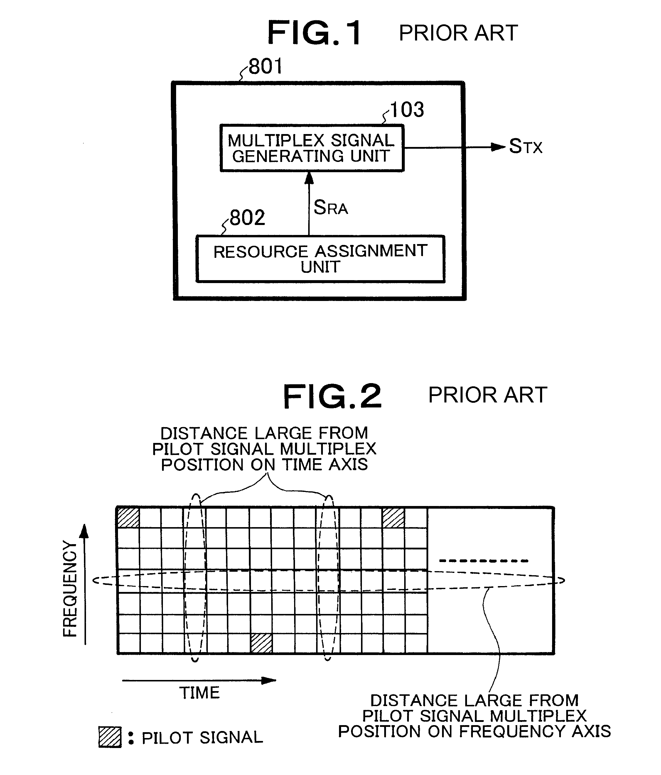
In the case where a radio resource distant from the pilot signal multiplex position on time axis or frequency axis are assigned to such terminals for data communication, therefore, the resource assignment method described above poses the problem that the channel estimation accuracy at the receiving end is deteriorated.
Although this accuracy can be improved by reducing the intervals at which the pilot signals are inserted, the problem of deterioration of transmission efficiency arises.

Method used


Image

  • Resource assignment method for communication system adapted for change of channel
  • Resource assignment method for communication system adapted for change of channel
  • Resource assignment method for communication system adapted for change of channel

Examples


embodiment 1

(Embodiment 1)

[0044]FIGS. 4 and 5 are block diagrams showing the configuration of the multiplex signal generating unit 103 and the resource selector 104 according to a first embodiment of the invention. FIG. 4 shows the configuration using OFDM as the transmission method described above with reference to the background art.

[0045]In FIG. 5, an information extraction unit 301, supplied with the channel information 1SCI1 to NSCIN, extracts the change amount of the channel of the first to Nth terminals on time and frequency axes, and outputs the time change information 1STD1 to NSTDN and the frequency change information 1SFD1 to NSFDN, respectively. The ranking units 302, 303, supplied with the time change information 1STD1 to NSTDN and the frequency change information 1SFD1 to NSFDN, rearrange them in the order of magnitude of the change amount and output the ranking of the change in the first to Nth terminals with time and frequency as time ranking information STR and frequency rankin...

embodiment 2

(Embodiment 2)

[0065]FIG. 8 is a diagram showing a resource selector 104 according to a second embodiment of the invention. The multiplex signal generating unit 103 has the configuration shown in FIG. 4 like the first embodiment.

[0066]In FIG. 8, an information extraction unit 301, supplied with the channel information 1SCI1 to NSCIN, extracts the change amount at the first to Nth terminals on time and frequency axes on the channel and outputs the time change information 1STD1 to NSTDN and the frequency change information 1SFD1 to NSFDN, respectively.

[0067]Group selectors 601, 602, supplied with the time change information 1STD1 to NSTDN and the frequency change information 1SFD1 to NSFDN, respectively, divide the first to Nth terminals into M groups in accordance with the time change information 1STD1 to NSTDN and K groups in accordance with the frequency change information 1SFD1 to NSFDN, and output the time group information STGR and the frequency group information SFGR, respective...


PUM


Abstract

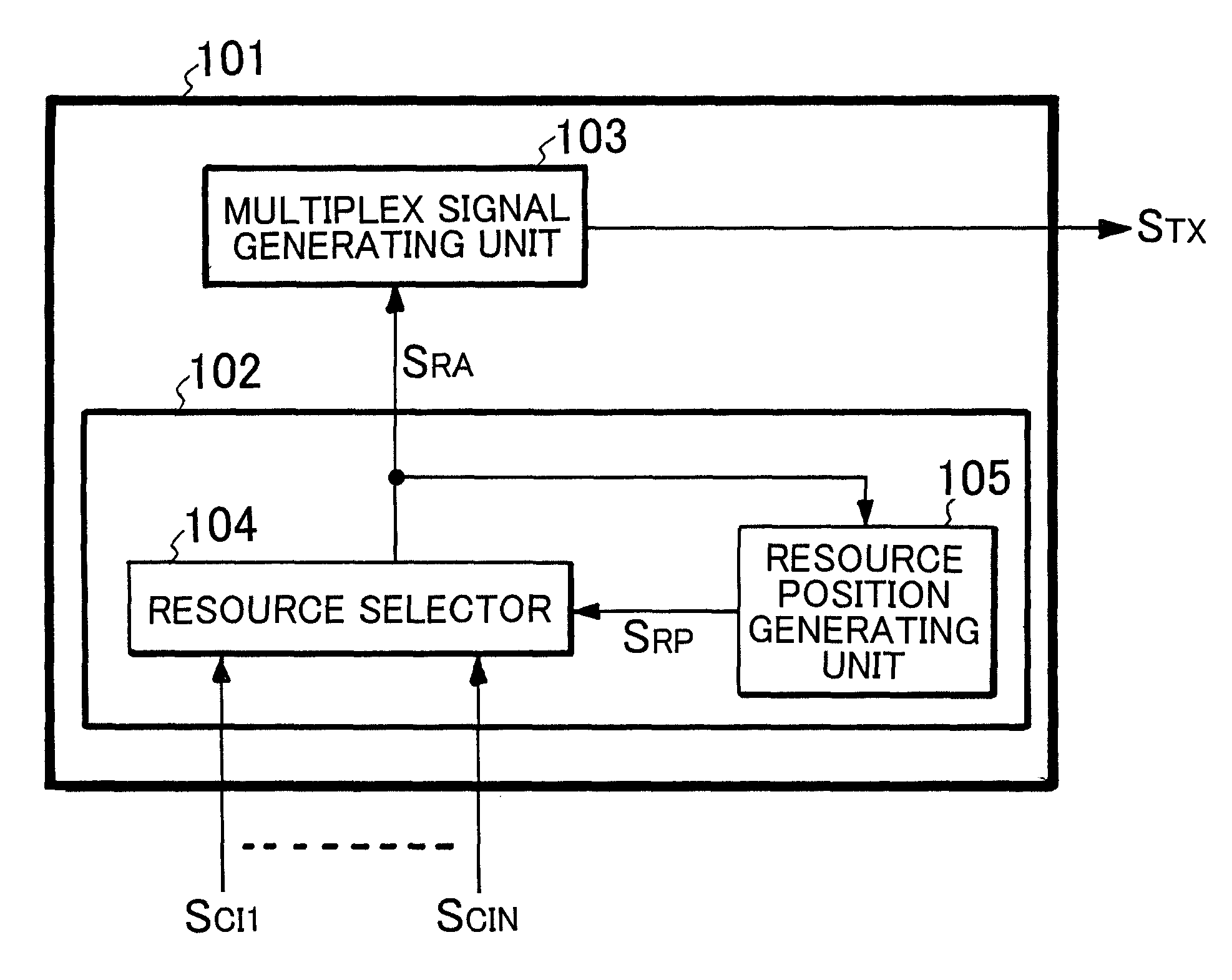
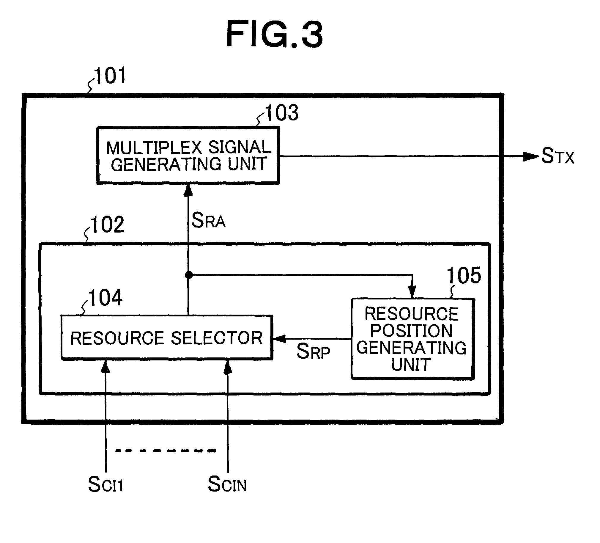
A resource assignment method for a communication system provides a method to realize an estimate of channel with high accuracy for terminals which change channels rapidly. A resource assignment unit (102), supplied with channel information ISCI1 to NSCIN, determines assignment of resources to a first to a Nth terminals and outputs a resource assignment information SRA. A multiplex signal generating unit (103), supplied with the resource assignment information SRA, outputs a transmission signal STX. A resource selector (104), supplied with the channel information 1SCI1 to NSCIN and the relative position information SRP, determines the assignment of resources to the first to Nth terminals and outputs the resource assignment information SRA. A resource position generating unit (105), supplied with the resource assignment information SRA, calculates a relative position of an empty resource with respect to a multiplex position of a pilot signal and outputs the relative position information SRP.

Description

[0001]This application is based upon and claims the benefit of priority from Japanese patent application No. 2005-102801, filed on Mar. 31, 2005, the disclosure of which is incorporated herein in its entirety by reference.TECHNICAL FIELD[0002]This invention relates to a resource assignment method for a communication system of which a communication apparatus transmits signals to a plurality of terminal units and assigns the resources adaptively based on channel information corresponding to each of the plurality of terminal units.BACKGROUND ART[0003]In the conventional radio communication system, a pilot signal is used as a known signal to estimate the channel. In the communication with a plurality of terminals sharing a radio resource, a method of multiplexing the pilot signal at predetermined intervals on the transmission data multiplexed for multiple users is known as a method of multiplexing the pilot signal shared and the transmission data to a plurality of terminals. An explanat...

Claims


Application Information

Patent Timeline
Patent Type & Authority Patents(United States)
IPC IPC(8): H04W4/00H04W72/06
CPCH04L5/0044H04L5/006H04B17/382H04L25/0222H04L5/0085H04L5/0007H04L5/0039H04L5/0048H04L25/0226H04L25/0232H04W72/06H04W72/563H04W72/51
Inventor KAKURA, YOSHIKAZU
Owner NEC CORP
Why Eureka
Try Eureka