Pessary applicator providing low placement

a technology of pessary and applicator, applied in the field of pessary applicators, can solve the problems of stress incontinence, inconvenient wearing of pads or diapers, and widespread problem of urinary incontinence,

Inactive Publication Date: 2006-07-20
PROCTER & GAMBLE CO
View PDF16 Cites 12 Cited by
  • Summary
  • Abstract
  • Description
  • Claims
  • Application Information

AI Technical Summary

Problems solved by technology

Urinary incontinence is a widespread problem among females.
While many different factors may contribute to the development of stress incontinence, stress incontinence is both aggravating and unpleasant for women, and it can also be embarrassing.
Many women wear sanitary pads or diapers in order to deal with incontinence, though this is not a real solution to the problem.
Wearing pad or diapers has are inconvenient and have side effects of skin irritation and odor limiting her social involvement and reducing her self esteem.
Some cases of incontinence are treated surgically but have the normal risks associated with surgery, such as infection, and results are often not permanent.
Shortcomings of these types of devices include the fact that they must be removed in order to empty the bladder and replaced with a new device which proves inconvenient and costly, they are susceptible to causing infection, and they often cause irritation to body tissue.
This approach has the significant disadvantage of not reliably controlling the insertion of the pessary into the vagina where it comfortable and effective.
Current pessary applicators place the pessary above the cervix where a pessary is not effective because it neither supports the prolapsed uterus nor does it apply pressure against the urethra nor does it help to straighten any “kinks” in the urethra.
Furthermore, if the pessary is placed too low, it can become exceedingly uncomfortable.
If the pessary is placed too high in the vagina and lodges to one side of the uterus, the reduction of urine leakage is not substantially improved because it cannot effectively support the urethra, uterus and bladder.
When the pessary is placed too low in the vaginal cavity, the pessary can cause bodily discomfort to the wearer because of the pressure exerted from the vaginal sphincter muscles.

Method used


Image

  • Pessary applicator providing low placement
  • Pessary applicator providing low placement
  • Pessary applicator providing low placement

Examples


Embodiment Construction

[0027] Section A will provide terms which will assist the reader in best understanding the features of the invention but not to introduce limitations in the terms inconsistent with the context in which they are used in this specification. These definitions are not intended to be limiting. Section B will discuss the pessary applicator of the present invention. Section C will discuss the Force Test Method. Section D will discuss the Length Test Method.

A. Terms

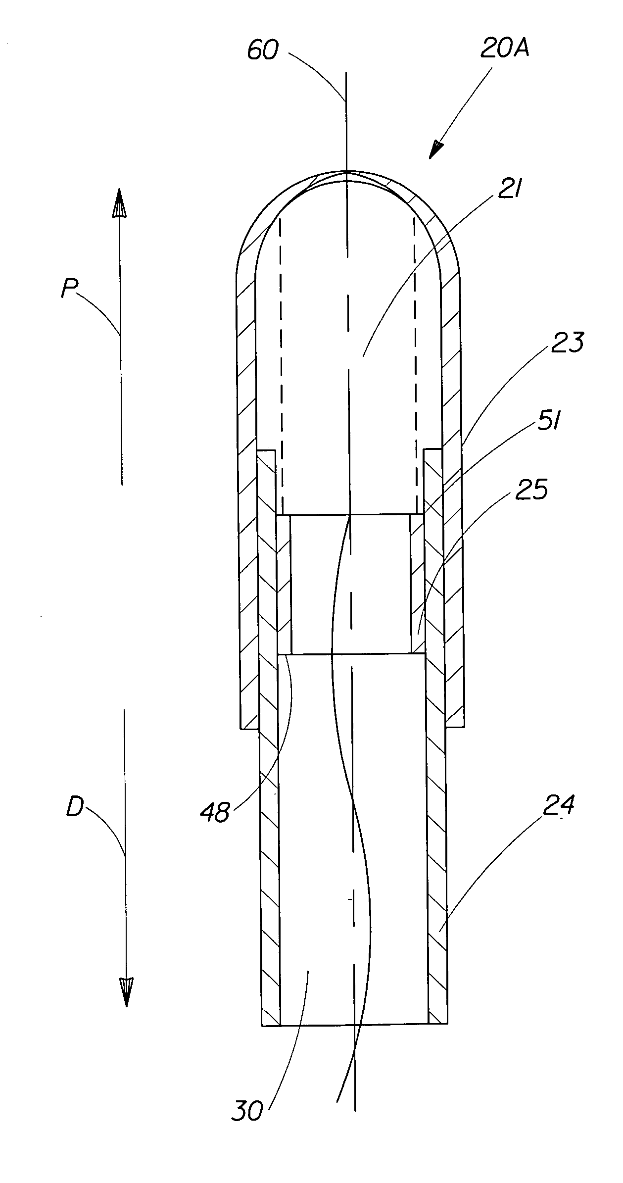
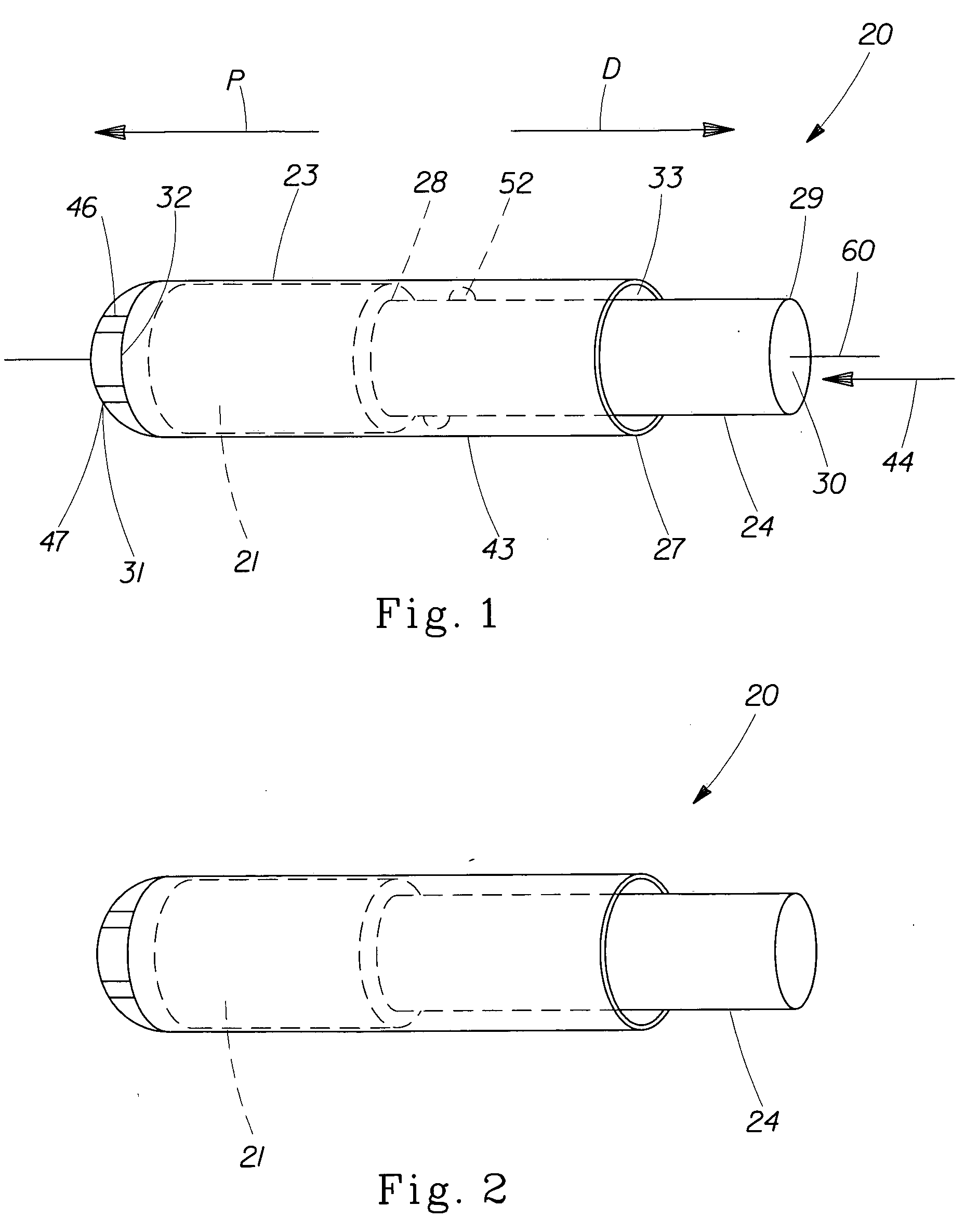
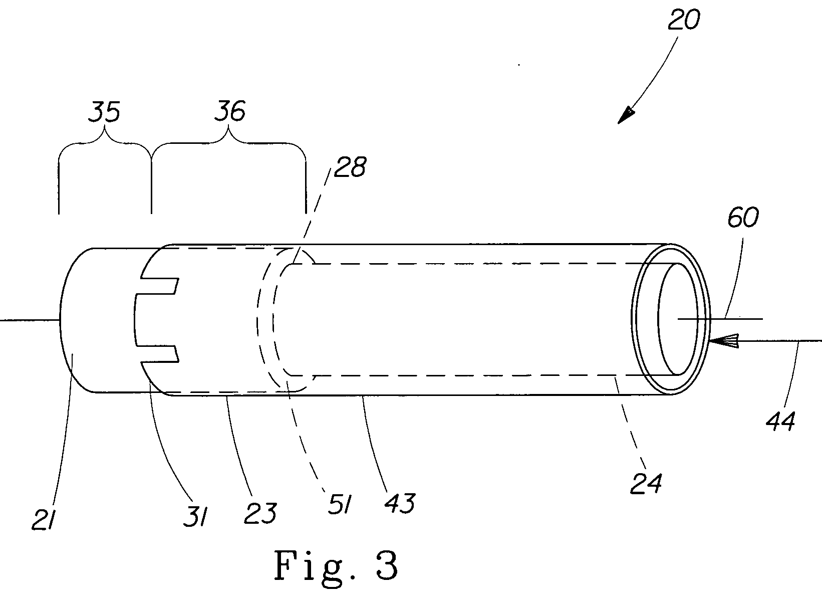
[0028] As used herein, the term “pessary” refers to any type of non absorbent vaginal insert for the purpose of reducing urine leakage. Such pessaries may be have any variety of shapes and sizes including cylinders, ovate, spherical, tubular, annual rings, “U” shaped, cup shaped, rings, cubes or donut shaped. They function by direct application of support, level force, expansion of the device by selection of material or by inflation of the device.

[0029] As used herein, the terms “vaginal cavity” and “within the vagina” refer ...


PUM


Abstract

A pessary applicator for positioning a pessary inside a vaginal cavity. The pessary applicator includes an outer member disposed co-axially with an inner member for insertion of the pessary into the vaginal cavity. The inner member is slidable within the outer member wherein at least 15% of a length of the pessary remains in the outer member when the inner member is fully engaged with the outer member to define a remaining portion of the pessary. The remaining portion of the pessary requires a force of less than about 0.30 N to be removed from the pessary applicator. Alternatively, when the inner member is fully engaged with the outer member to define a remaining portion of the pessary, the remaining portion of the pessary requires a force of less than about 0.04 N / mm to be removed from the outer member.

Description

CROSS REFERENCE TO RELATED APPLICATIONS [0001] This application is a continuation-in-part of U.S. application Ser. No. 10 / 860,910, filed Jun. 4, 2004, pending.FIELD OF INVENTION [0002] This invention relates to an applicator for proper placement of a urinary incontinent pessary into the vagina. BACKGROUND OF THE INVENTION [0003] Urinary incontinence is a widespread problem among females. It is estimated that up to 50% of women occasionally leak urine involuntarily, and that approximately 25% of all women will seek medical advice at some point in order to deal with the problem. The two primary types of incontinence are stress incontinence and urge incontinence which have different origin and can occur as separate or combined conditions. Treating one condition does not necessarily mean the other condition has been treated. Incontinence is more prevalent among women who have given birth to one or more children. There are two primary demographic factors that are associated with female u...

Claims


Application Information

Patent Timeline
Patent Type & Authority Applications(United States)
IPC IPC(8): A61F13/20A61F13/26
CPCA61F13/26
Inventor OSBORN, THOMAS WARD IIIGANN, DIANA LYNNE
Owner PROCTER & GAMBLE CO
Why Eureka
Try Eureka