
Injection molding system data management method

a technology of injection molding and data management, applied in the field of injection molding system data management, can solve the problems of system failure to operate, mismatch between molding conditions and robot teaching program and/or setting data, etc., and achieve the effect of preventing discrepancies and easy reading

Active Publication Date: 2006-07-20
FANUC LTD
View PDF0 Cites 9 Cited by
  • Summary
  • Abstract
  • Description
  • Claims
  • Application Information

AI Technical Summary

Benefits of technology

[0011] A first embodiment of the data management method according to the present invention comprises a step transferring, when an operation for saving the set of molding conditions is performed through an operation means on the injection molding machine side, a teaching program and / or setting data for the molded-product removing robot which correspond to the set of molding conditions, to the controller of the injection molding machine via the communication means, and step of saving the set of molding conditions for the injection molding machine and the teaching program and / or setting data for the molded-product removing robot in association with each other in a storage means.
[0018] As the data management method for injection molding systems according to the present invention comprises the above steps, a set of molding conditions and its related robot teaching program and / or setting data can be saved in association with each other and easily read, thereby preventing occurrence of a discrepancy between the set of molding conditions and the robot teaching program and / or setting data resulting from an operation error.

Problems solved by technology

If a set of molding conditions or a robot teaching program not matching the mold is set by mistake, the system will not operate.
However, the set of molding conditions and the robot teaching program and / or setting data are stored in separate files, so even if the files are managed by mold numbers or the like, an error made in specifying corresponding numbers or an error in a file reading operation can produce a mismatch between the molding conditions and the robot teaching program and / or setting data.

Method used


Image

  • Injection molding system data management method
  • Injection molding system data management method
  • Injection molding system data management method

Examples


Embodiment Construction

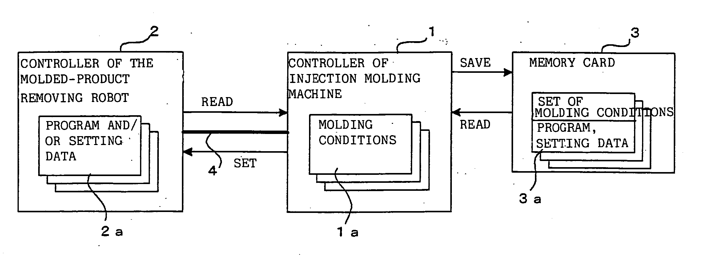
[0022]FIG. 1 is a schematic block diagram of an injection molding system executing one example of the data management method of the present invention. In the injection molding system shown in FIG. 1, the controller 1 of an injection molding machine and the controller 2 of a molded-product removing robot are connected via communication means 4 such as an Ethernet (registered trademark) network. The controller 1 of the injection molding machine is provided with a memory card interface, through which a memory card 3 (storage means) for storing molding conditions, programs, and setting data is connected to the controller.

[0023] To mold a product, the controller 1 of the injection molding machine controls the driving of the injection molding machine based on a set of molding conditions 1a which is stored. To remove the molded product from the mold, the controller 2 of the molded-product removing robot controls the driving of the robot based on a robot teaching program and / or setting dat...


PUM

PropertyMeasurementUnit
Moldableaaaaaaaaaa

Abstract

A controller of an injection molding machine and a controller of a molded-product removing robot are connected to each other via communication means. When a molding condition save command is entered from the controller of the injection molding machine, a folder with a management number is created on a memory card, and molding conditions stored in the controller of the injection molding machine are saved in the folder. A teaching program and / or setting data stored in the robot controller is read via the communication means and saved in the same folder. When a molding condition read command is entered, data is read from a specified folder, molding conditions are set in the controller of the injection molding machine, and a teaching program etc. are set in the robot controller via the communication means.

Description

BACKGROUND OF THE INVENTION [0001] 1. Field of the Invention [0002] The present invention relates to a data management method for an injection molding system including an injection molding machine and a molded-product removing robot that removes a product molded by the injection molding machine. [0003] 2. Description of the Related Art [0004] One known type of injection molding system consists of an injection molding machine and a robot that removes, from a mold, a product molded by the injection molding machine. In this injection molding system, a mold matching the products to be molded is mounted on the injection molding machine, and molding conditions (clamping force, mold open position, injection speed, hold pressure, metering speed, metering position, etc.) for that mold are set in the injection molding machine. When brought into operation, the injection molding machine molds products by performing injection molding based on the molding conditions that have been set. [0005] In ...

Claims


Application Information

Patent Timeline
IPC IPC(8): B29C45/00B29C45/42B29C45/76
CPCB29C45/7626B29C45/766B29C2045/7633B29C2945/76498B29C2945/76505B29C2945/76568B29C2945/76595B29C2945/76846B29C2945/76859B29C2945/76913B29C2945/76949G05B19/41825G05B2219/39105Y02P90/02
Inventor IKEDA, YOSHITAKAKOSAKA, TETSUYA
Owner FANUC LTD
Learn More