
Self-calibrating transducer system and musical instrument equipped with the same

Active Publication Date: 2006-07-27
YAMAHA CORP
View PDF12 Cites 31 Cited by
  • Summary
  • Abstract
  • Description
  • Claims
  • Application Information

AI Technical Summary

Benefits of technology

[0006] It is therefore an important object of the present invention to provide a position transducer system, which is self-calibrated for output characteristics. It is also an important object of the present invention to provide a musical instrument equipped with the position transducer system.
[0006] It is therefore an important object of the present invention to provide a position transducer system, which is self-calibrated for output characteristics. It is also an important object of the present invention to provide a musical instrument equipped with the position transducer system.

Problems solved by technology

These phenomena are unavoidable so that a countermeasure is required for the position transducer.

Method used


Image

  • Self-calibrating transducer system and musical instrument equipped with the same
  • Self-calibrating transducer system and musical instrument equipped with the same
  • Self-calibrating transducer system and musical instrument equipped with the same

Examples


first embodiment

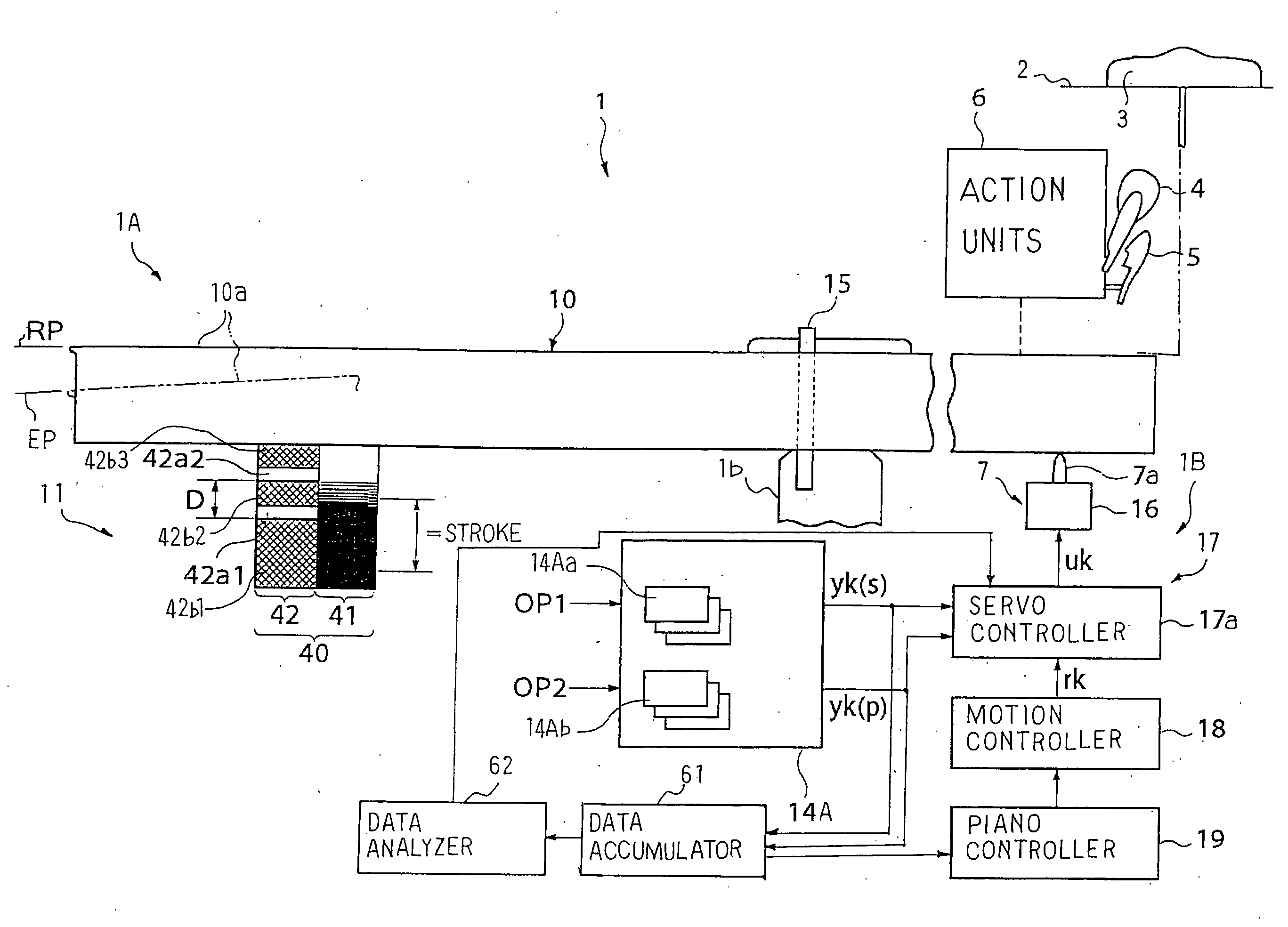
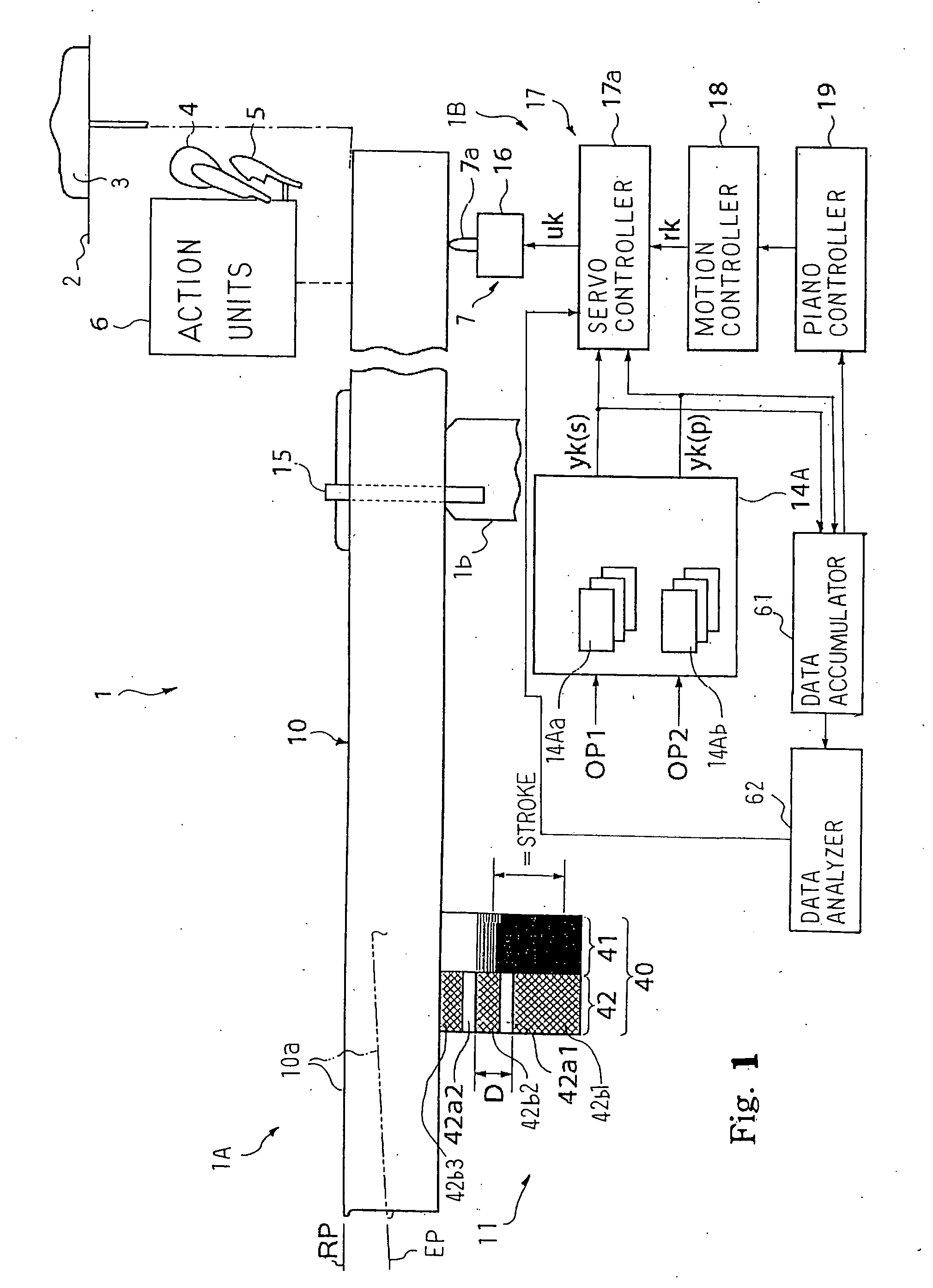
[0028] Referring to FIG. 1 of the drawings, an automatic player piano 1 embodying the present invention largely comprises an acoustic piano 1A and an electric system 1B. A human player plays a music passage on the acoustic piano 1A, and acoustic piano tones are produced along the music passage in the acoustic piano 1A. The electric system 1A serves as an automatic player, and the automatic player plays a music passage on the acoustic piano 1A without the fingering of the human player.

Structure of Acoustic Piano

[0029] The acoustic piano 1A includes strings 2, dampers 3, hammers 4, action units 6, which have respective back checks 5, and a keyboard 10. Plural keys 10a are incorporated in the keyboard 10, and independently pitch up and down on a balance rail 1b. In this instance, eighty-eight keys 10a are provided on the keyboard 10. While the player depresses the front portions of the keys 10a, the keys travel on respective trajectories toward the end positions EP. Balance pins 15 u...

second embodiment

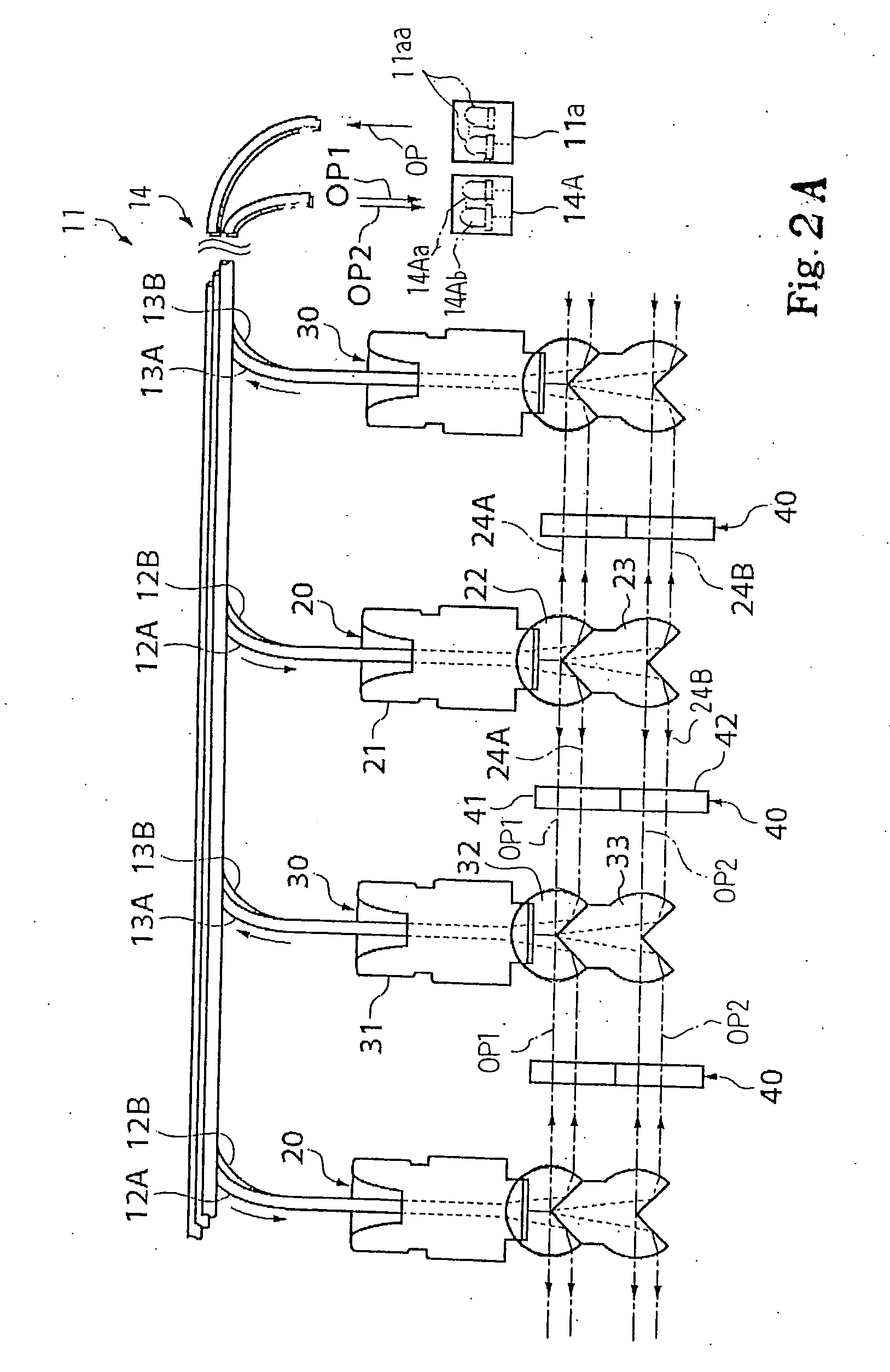
[0088] Turning to FIG. 4 of the drawings, a position transducer system embodying the present invention is used in monitoring key motion in an automatic player piano 80. The automatic player piano 80 largely comprises an acoustic piano 80A and an electric system 80B. The acoustic piano 80A and electric system 80B are similar to the acoustic piano 1A and electric system 1B except for optical position transducers 50 and optical modulators 40A. The optical position transducer 50 is similar to the optical position transducer 14 except for a reflection type sensor head unit 50a and an optical modulator 40A. The light emitting unit 11a, pairs of optical fibers 12A / 12B, pairs of optical fibers 13A / 13B and light detecting unit 14A also form parts of the optical position transducers 50. However, light radiating sensor heads and light receiving sensor heads have only the second light radiating ports 23 and second light receiving ports 33. In other words, the first light radiating ports 22 and ...


PUM


Abstract

A self-calibrating key sensor system is constituted by an optical modulator, optical position transducers, a data accumulator and a data analyzer, and the optical modulator has a gray scale section to produce a key position signal varied together with the keystroke and an absolute data section to produce a calibration signal representative of a strictly adjusted distance between transparent areas of the absolute data section; the data accumulator accumulates discrete values of the calibration signal and discrete values of the key position signal together with the sampling time, and the data analyzer determines the gradient of the key position signal on the basis of peaks of the calibration signal produced at both ends of the strictly adjusted distance so as to estimate the true distance between the rest and end positions.

Description

FIELD OF THE INVENTION [0001] This invention relates to a transducer system and, more particularly, to a transducer system suitable for musical instruments. DESCRIPTION OF THE RELATED ART [0002] Various hybrid musical instruments are offered to music fans. The hybrid musical instrument is a combination between an acoustic musical instrument and an electric system. Typical examples are disclosed in Japanese Patent Application laid-open Nos. 2002-156967 and Hei 6-149234. The prior art position transducers are of the type converting variation in the amount of incident light to the potential level of an electric signal. [0003] Both prior art position transducers are incorporated in the hybrid pianos, and monitor the hammers of the pianos. Each of the prior art position transducer is constituted by an optical modulator and a photo coupler. The optical modulator is connected to the hammer, and is moved together with the hammer. The photo coupler is supported by the piano cabinet, and is s...

Claims


Application Information

Patent Timeline
Patent Type & Authority Applications(United States)
IPC IPC(8): G10H3/06
CPCG01D18/006G01D18/008G10F1/02
Inventor MURAMATSU, SHIGERU
Owner YAMAHA CORP
Learn More