Device for generating pyrotechnic effects

a technology of pyrotechnics and devices, applied in the field of devices for generating pyrotechnics, can solve the problems of high cost and complicated production of such known devices, and the difficulty of manufacturing such devices, and achieve the effect of simple production and quite easy manufacturing

Active Publication Date: 2006-07-27
CHEMRING DEFENCE GERMANY
View PDF8 Cites 13 Cited by
  • Summary
  • Abstract
  • Description
  • Claims
  • Application Information

AI Technical Summary

Benefits of technology

This patent describes a device that generates pyotechtic effects by housing multiple pyrotechnic charges and an ignition system within a common envelope consisting of several layers. Each layer acts as its own insulation, making it easy to assemble and use the device without requiring extra parts like an ignition module. The design allows for quick production and easy arrangement of components. Additionally, the layers can be conveniently sized by connecting them and then cutting them into desired shapes. Overall, this device provides a simplified way to create powerful pyotechtic effects.

Problems solved by technology

The technical problem addressed in this patent is how to create a device for producing pyrotechnic effects that is easy and reliable to operate with multiple effects placed within one device.

Method used


Image

  • Device for generating pyrotechnic effects
  • Device for generating pyrotechnic effects
  • Device for generating pyrotechnic effects

Examples


Embodiment Construction

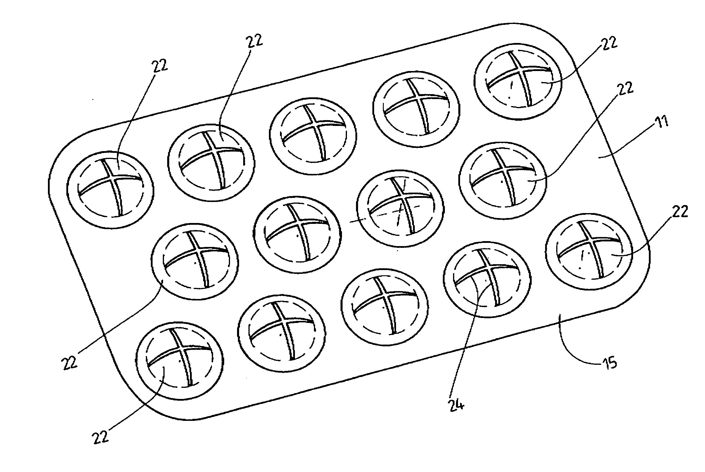
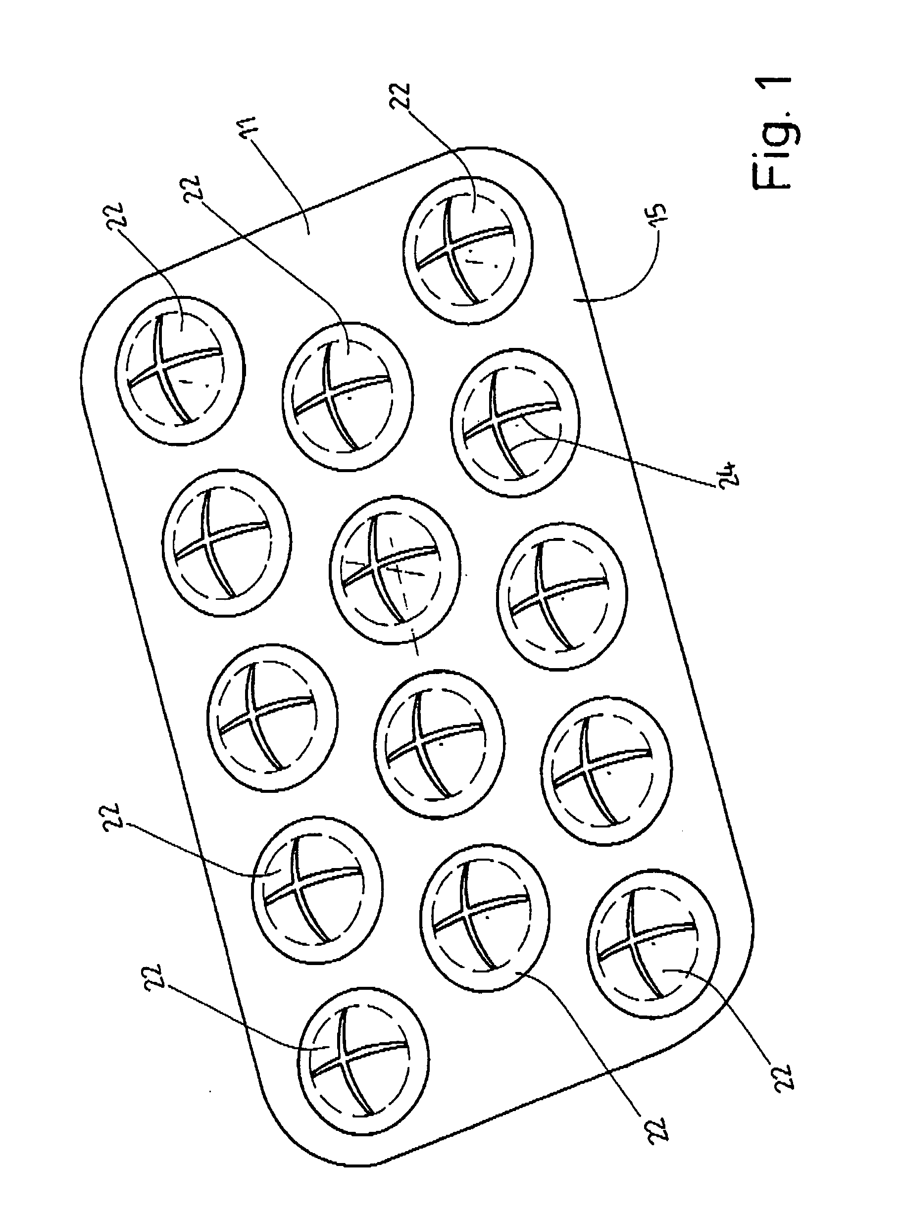
[0031] The devices shown in the figures are employed for training purposes in civil defense and military exercises, particularly in the interior of buildings when, for example, soldiers or police officers carry out realistic simulations of house-to-house combat or the storming of a building. Here the device is employed to generate the pyrotechnic simulation of gunfire, explosions or even stun grenades. But the possible uses of the device according to the invention is not limited to these example but can also be employed for other common simulations.

[0032] The shown device generates acoustic and / or optic simulations by means of igniting pyrotechnic charges. The devices shown in the figures have a plurality of pyrotechnic charges. The number of pyrotechnic charges in each device can vary according to the type of simulation. It is also conceivable that the device has only a single pyrotechnic charge and is thus employed only for the simulation of a single explosion or the like.

[0033]...


PUM


Abstract

A simple device for generating pyrotechnic effects, in which an enveloping body (11) is formed from a plurality of interconnected plate-like layers between which the pyrotechnic charges (10) as well as the igniter means (12) are embedded. A configuration of the igniter means (12) as heating resistors, in particular as heating resistors whose conductors run in a meandering path. Such igniter means (12) are particularly suitable for use in the formation of a plate-like enveloping body consisting of a plurality of layers. By virtue of this enveloping body, the device assumes a shape comparable to that of a credit card or bank card.

Description


Claims


Application Information

Patent Timeline
Owner CHEMRING DEFENCE GERMANY
Why Eureka
Try Eureka