Applicator for make-up remover

Inactive Publication Date: 2006-07-27
LOREAL SA
View PDF7 Cites 58 Cited by
  • Summary
  • Abstract
  • Description
  • Claims
  • Application Information

AI Technical Summary

Benefits of technology

[0015] Preferably, under the effect of resilient return forces generated by the applicator, and when the folding force is relaxed, the application surface reverts to its initial shape.
[0016] In a preferred embodiment, in its initial form, with no force exerted, the application surface can be flat, whereas under the effect of a first folding force, exerted on the support in a direction opposite the application surface, the application surface can include at least one convex transverse cross-section and at least one concave lengthwise cross-section.
[0017] Alternatively, in its initial form, with no force exerted the application surface can be flat, whereas under the effect o

Problems solved by technology

In these cases, the removal of make-up can be expensive as it requires the use of numerous cotton pads or wipes to properly remove the make-up, ensuring that all of the make-up and all of the make-up remover composition latterly applied is removed.
Moreover, these cotton pads or wipes are typically not subsequently re-used.
In fact, given that the make-up remover compositions and the removed make-up are generally liquid and viscous, they irreversibly degrade and soil the initial aerated structure of the cotton or wipe.
Furthermore, as the cotton pads used with such com

Method used


Image

  • Applicator for make-up remover
  • Applicator for make-up remover
  • Applicator for make-up remover

Examples


Example

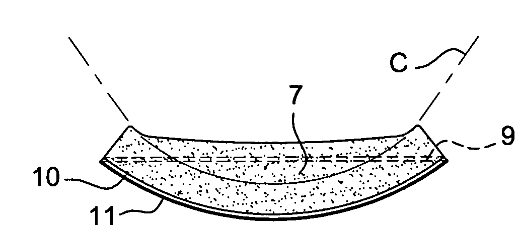
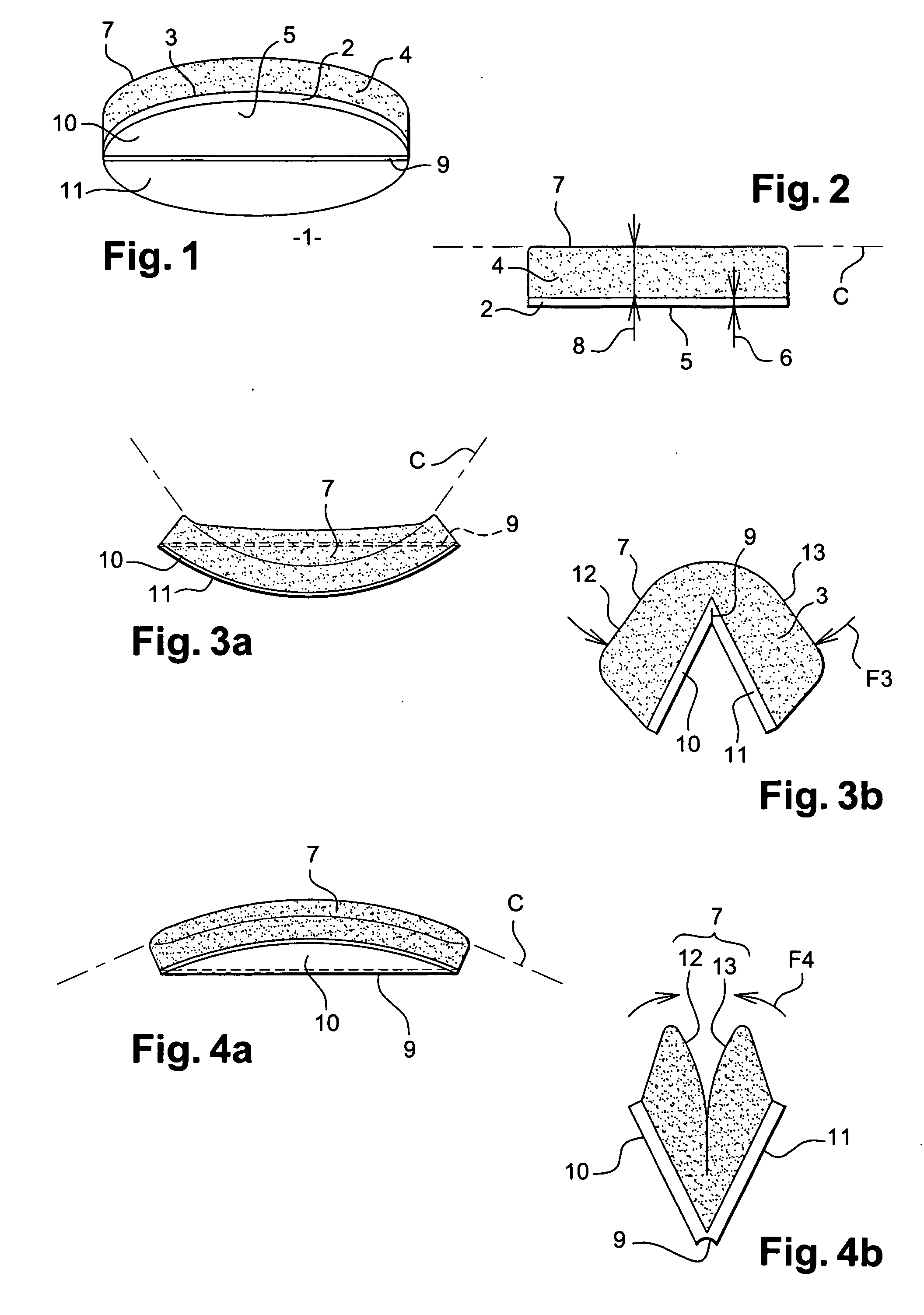
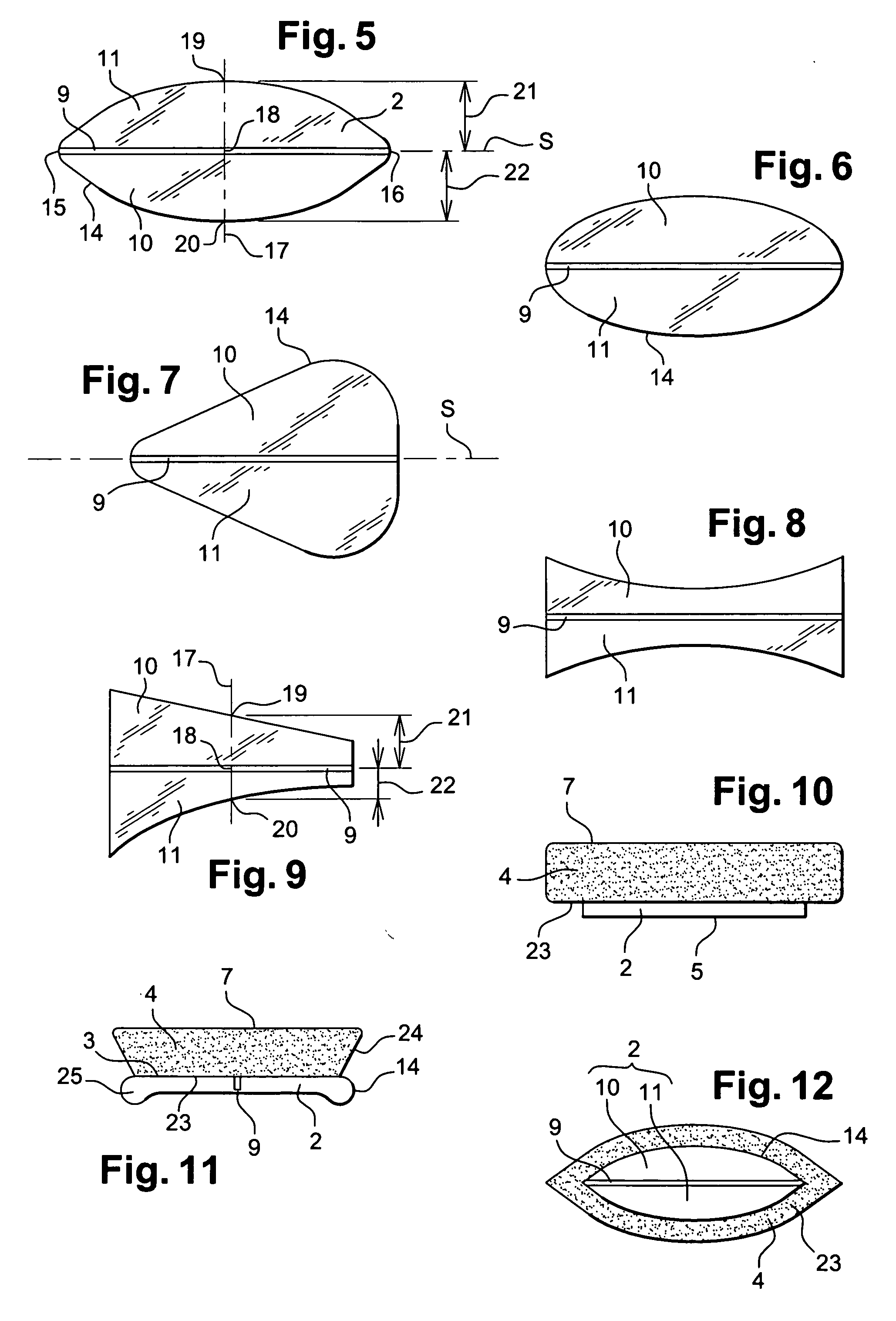
[0046]FIG. 1 shows an applicator 1 including a support 2 on one face 3 of which is affixed an applicator element 4.

[0047] The face 3 of the support 2 is substantially flat. Preferably, the support 2 is in the form of a plate then having a second face 5 opposite the face 3. In particular, the thickness 6, as depicted in FIG. 2, of this plate forming the support 2 can be between 0.3 mm and 2 mm, and preferably of the order of 0.5 mm.

[0048] The applicator element 4 presents an application surface 7, this surface 7 being substantially opposite the second face 5. In particular, in the embodiments shown, the application surface 7 is substantially flat when the device is not subjected to any force, and in particular any folding force. In a storage position, with no force exerted, the application surface 7 is parallel to the second face 5. In particular, the thickness 8, as depicted in FIG. 2, of the applicator element 4 can be between 5 mm and 15 mm, and preferably of the order of 12 mm....


PUM


Abstract

An applicator includes a support on one face of which is attached a resiliently deformable applicator element presenting an application surface opposite the support. The support has a preferential folding axis such that, in response to a folding force exerted on the support, the applicator element is deformed so as to modify the transverse curvature of the application surface observed transversely to the axis. The lengthwise curvature of the application surface observed axially along the axis is also modified.

Description

CROSS-REFERENCE TO RELATED APPLICATIONS [0001] This application claims priority to French Application No. 0452997, filed Dec. 15, 2004 and U.S. Provisional Application No. 60 / 639,858, filed Dec. 29, 2004, the entire contents of both of which are hereby incorporated by reference.BACKGROUND OF THE INVENTION [0002] 1. Field of the Invention [0003] The present invention relates to an applicator for the application of a cosmetic product. For example, the applicator can be impregnated with a make-up remover product to facilitate the removal of make-up, and in particular to remove make-up from the eyes, eyelashes, eyebrows and eyelids. [0004] 2. Discussion of the Background [0005] The expression “cosmetic product” is understood to mean a product as defined in Council Directive 93 / 35 / EEC dated 13th Jun. 1993. [0006] It is known to use a make-up remover composition to remove make-up from the face. These compositions are either applied directly onto the face, in which case they are removed to...

Claims


Application Information

Patent Timeline
IPC IPC(8): A47K7/02
CPCA45D34/04A45D2200/1018A45D2200/1036A45D2200/1063
Inventor THIEBAUT, LAURE
Owner LOREAL SA
Why Eureka
Try Eureka