Spincast fishing reel with top-mounted quick-change line spool

Inactive Publication Date: 2006-07-27
DICKSON RICHARD M
View PDF25 Cites 79 Cited by
  • Summary
  • Abstract
  • Description
  • Claims
  • Application Information

AI Technical Summary

Benefits of technology

[0018] A new variant of a spincast fishing reel, which, according to the preferred embodiment, consists of a metal reel frame, which includes a helical and pinion gear box assembly, connected to a spring assisted spool release lever and fishing reel handle, and a centered spool support, which is spring-loaded, so that it can be extended upward through a hole passing through the pinion gear and into a top mounted, lidded line holding canister, which contains the plastic line dispenser spool purchased separately and made by the various fishing line manufacturers. The line dispenser spool is loaded directly through the hole in its center onto the proposed fishing reel's line spindle, so that the line dispenser spool can freely rotate. It should be noted that the tip of the proposed fishing spool support is a narrow flat-topped screw, which is screwed into threads bored into the line spindle, which is in the lidded line canister. The line spindle is thus held tightly in the lidded canister by means of spring tension exerted by the spring around the spool support in the reel body. Likewise, the pinion gear is kept in place by this same spring tension, since the spool support runs through the hollow pinion gear, before connecting to

Problems solved by technology

However, none of the prior art involves systems, which incorporate the plastic fishing line manufacturers' line dispenser spools directly into the fishing reel design, but instead either rely upon complicated cartridge and mechanical loading systems for getting the fishing line onto the fishing reel line spool or require extensive modification to the traditional fishing reel line spool design.
However, this is an external device not integrated directly into the body of the fishing reel design.
U.S. Pat. No. 5,911,378 to Plestan proposes a quick change open face spinning reel line spool However, this invention improves upon existing open face spinning reel li

Method used


Image

  • Spincast fishing reel with top-mounted quick-change line spool
  • Spincast fishing reel with top-mounted quick-change line spool
  • Spincast fishing reel with top-mounted quick-change line spool

Examples


Embodiment Construction

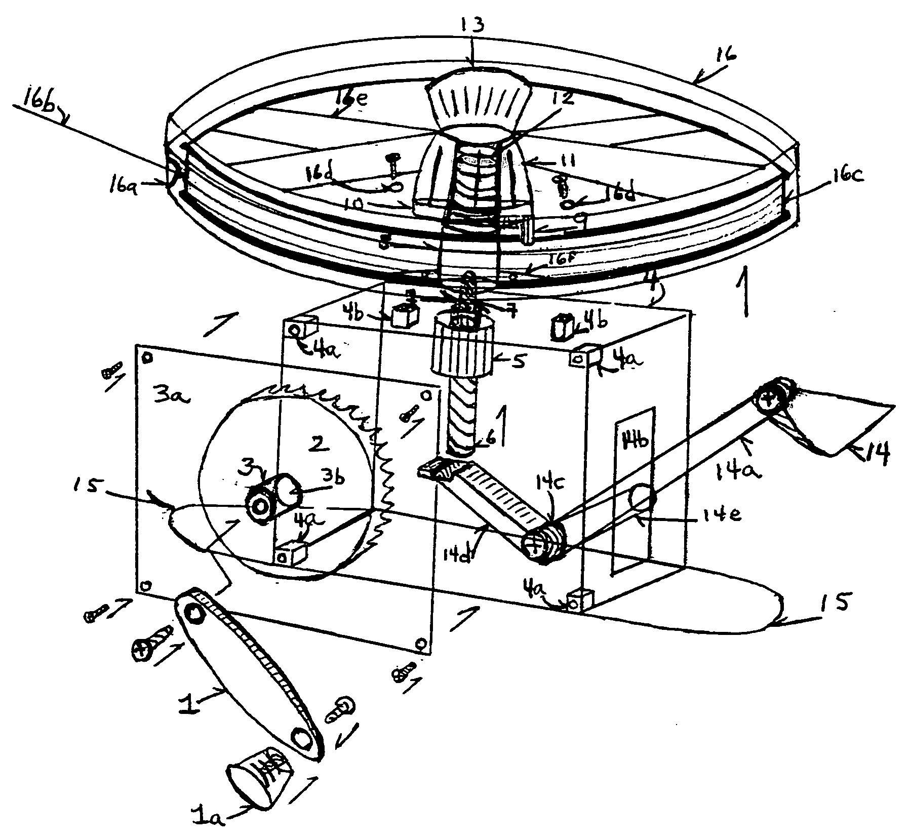
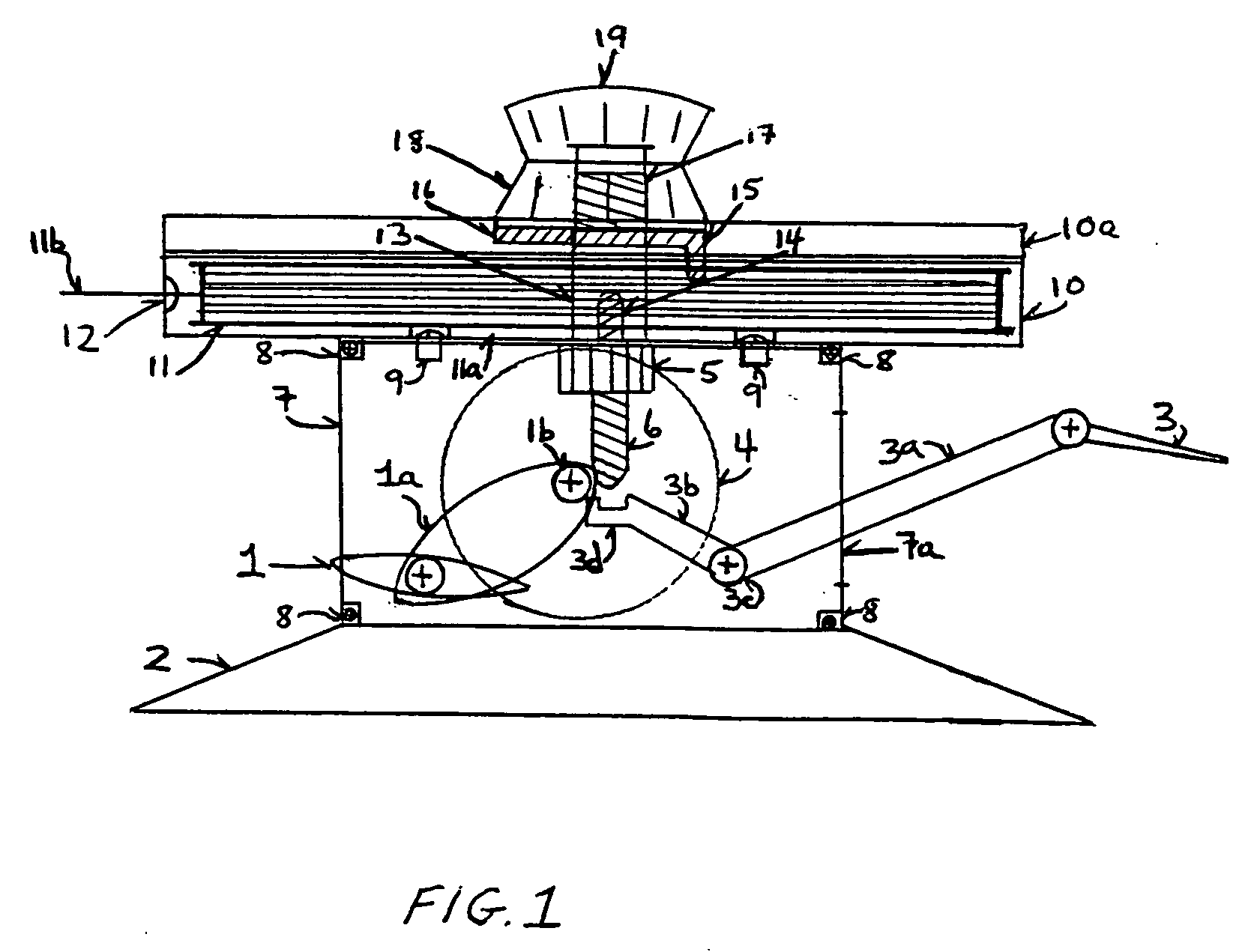
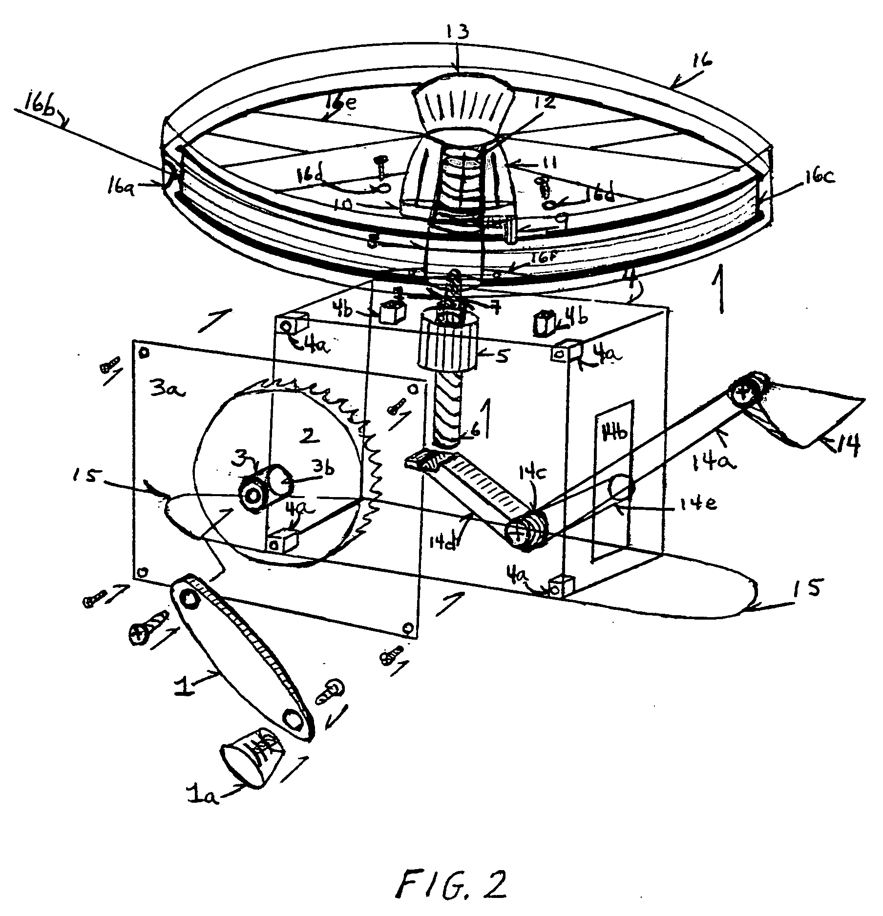
[0021] Now referring to FIGS. 1 and 2, both make adequate disclosure of the proposed fishing reel invention to someone with ordinary skill in the art. It should be noted that FIGS. 1 and 2 are not true to scale, but that by varying size and distances of component parts, improved performance will be achieved for the preferred embodiment of the proposed invention.

[0022] Referring to FIG. 1, the fishing reel handle 1 and the handle lever 1a, which is connected by a screw to the helical gear 4, located inside the reel body face plate 7. The reel seat is at 2. The spool release lever handle 3 connects to the long lever handle arm 3a, and passes out of the reel frame body through a slit manufactured in the reel frame 7a. The short lever arm 3b is mounted below the spring loaded spindle support 6. It should be noted that there is an indentation at the end of the short lever arm at 3d to catch and temporarily hold the line support hub 6 when the spool release lever 3 is depressed. A tensio...


PUM


Abstract

A spincast fishing reel consisting of a frame in which the line spool is mounted horizontally above the reel frame and gear box assembly inside a round, lidded line canister, positioned horizontal to the horizontal plane. The line spool used is a commercially available plastic line manufacturer's dispenser spool in lieu of an internal reel spool. The line dispenser spool is mounted on a central line spindle, inside the line canister. A drag thumb wheel button is mounted centrally atop the line canister, followed by a capstone quick release line spool twist knob, which is also connected to the line spindle inside the line canister. A spring mounted line release lever protrudes out the back side of the reel frame through an open slit in the reel frame cover. Cast line exits the top mounted line canister through a grommeted aperture mounted at the front, and facing the direction of the rod guides.

Description

CROSS-REFERENCE TO RELATED APPLICATIONS [0001] This application claims benefit of U.S. Provisional Applications Ser. Nos. 60 / 641,582 filed Jan. 4, 2005 and 60 / 495,256 filed Aug. 13, 2003.STATEMENT REGARDING FEDERALLY SPONSORED RESEARCH OR DEVELOPMENT [0002] Not applicable REFERENCE TO SEQUENCE LISTING, A TABLE OR A COMPUTER PROGRAM LISTING COMPACT DISK APPENDIX [0003] Not applicable BACKGROUND OF THE INVENTION [0004] 1. Field of the Invention [0005] The present invention relates to fishing reels, and more particularly closed faced fishing reels, commonly known as spincast reels, and to fishing reels which employ a quick-change spool system. [0006] Currently, fishing reels utilize a rigid spool integrated into the fishing reel for holding the fishing line. These fishing line spools are expensive to manufacture and are fitted into the body of the sport fishing reel. However, these line spools can generally be removed and replaced with auxiliary fishing line spools, spooled with fishin...

Claims


Application Information

Patent Timeline
IPC IPC(8): A01K89/01
CPCA01K89/003A01K89/015A01K89/0192
Inventor DICKSON, RICHARD M.
Owner DICKSON RICHARD M
Why Eureka
Try Eureka