
Metal detector with improved receiver coil

Inactive Publication Date: 2006-07-27
DIENCO
View PDF7 Cites 7 Cited by
  • Summary
  • Abstract
  • Description
  • Claims
  • Application Information

AI Technical Summary

Benefits of technology

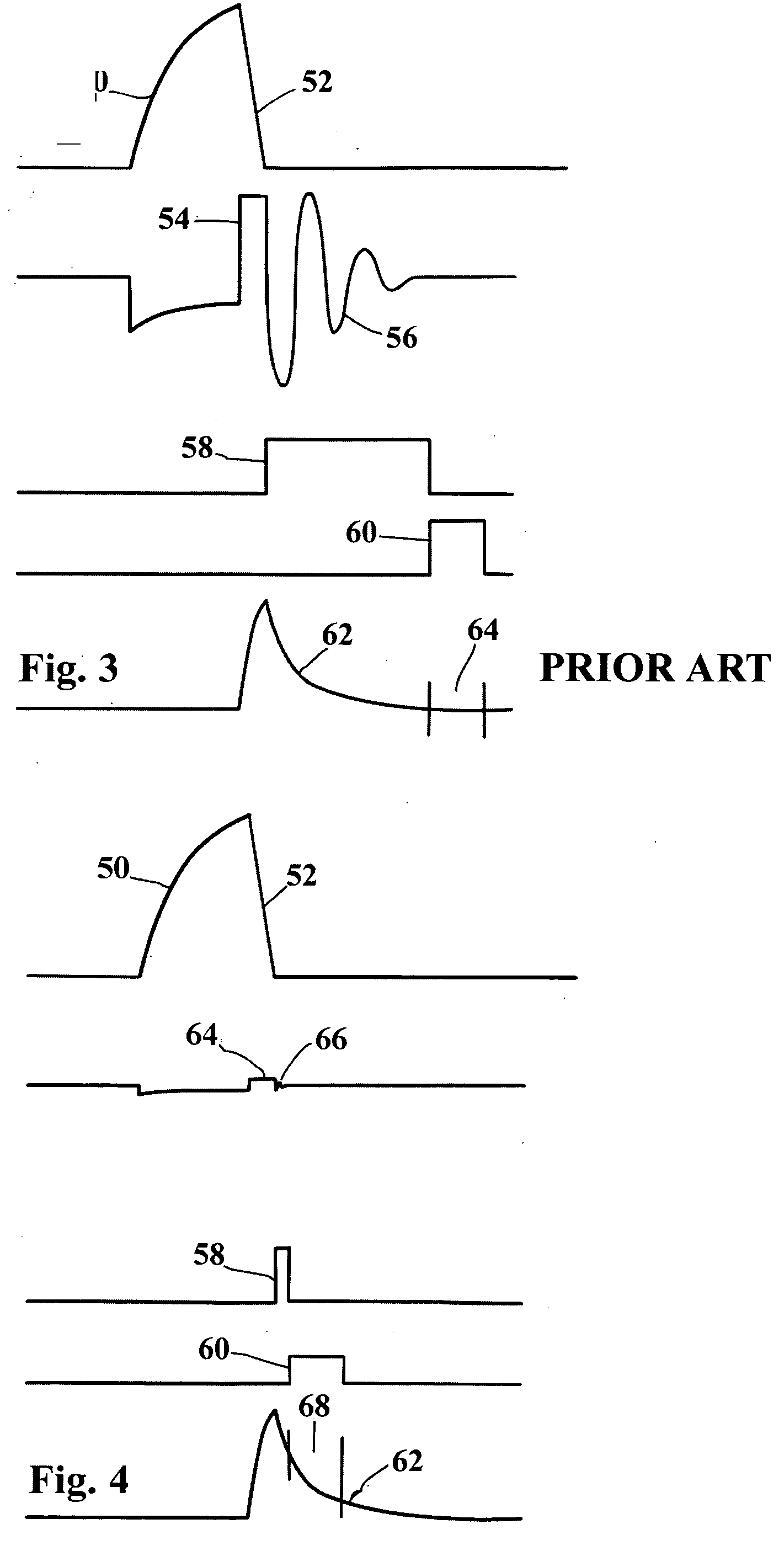
[0014] It is an object of the present invention to provide a metal detector with a coil configuration that retains its maximal ability to capture target signals, while minimizing the absorption of energy from the primary flux. The advantage derived from the invention is that the delay between the coil pulse and th

Problems solved by technology

The primary flux also induces a voltage in the receiver coil, and the target voltage cannot be effectively detected until the effects of the primary flux have substantially subsided.
Both of the above methods suffer from the drawback that the sensitivity of the detector is decrease

Method used


Image

  • Metal detector with improved receiver coil
  • Metal detector with improved receiver coil
  • Metal detector with improved receiver coil

Examples


Embodiment Construction

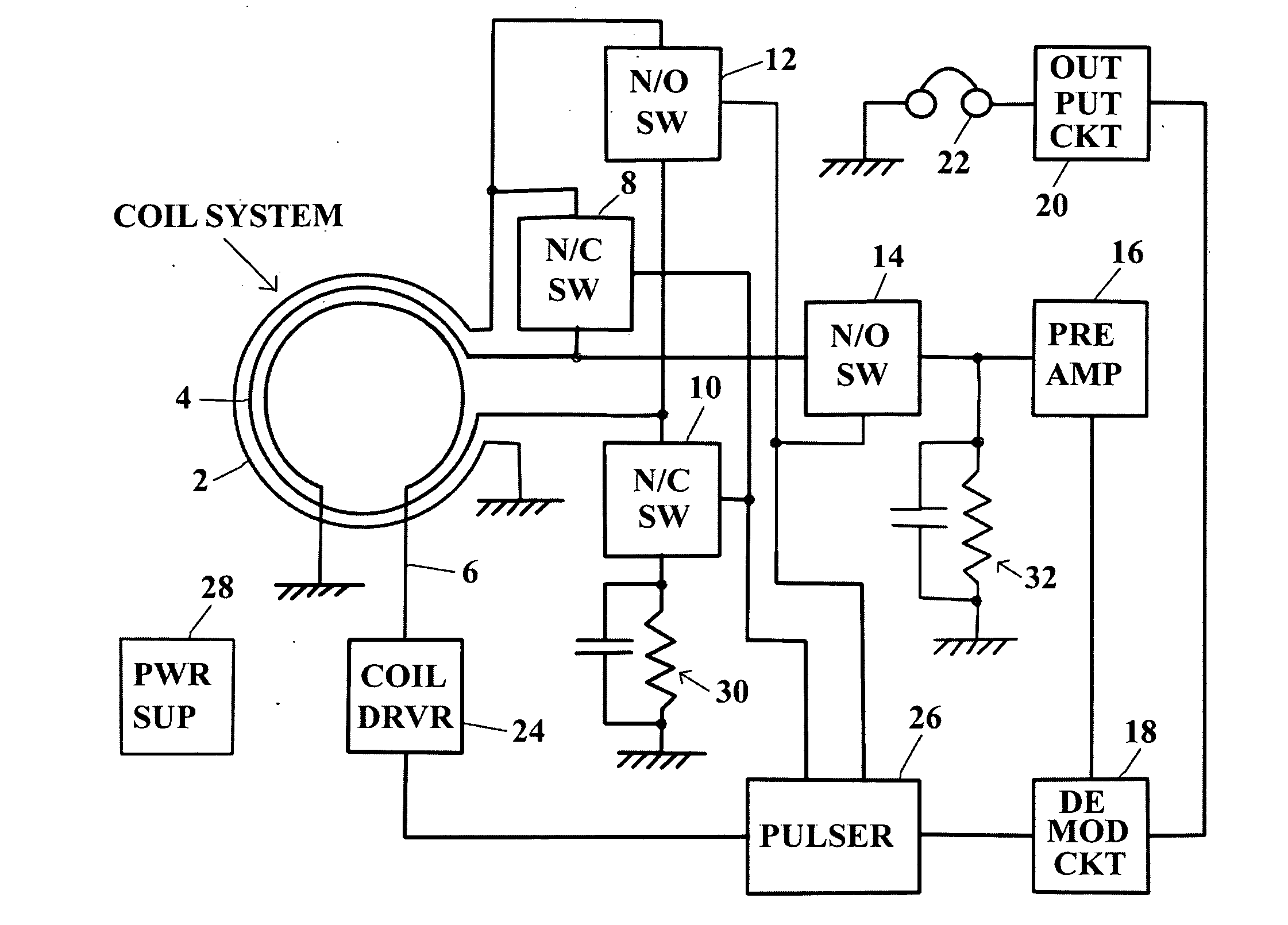
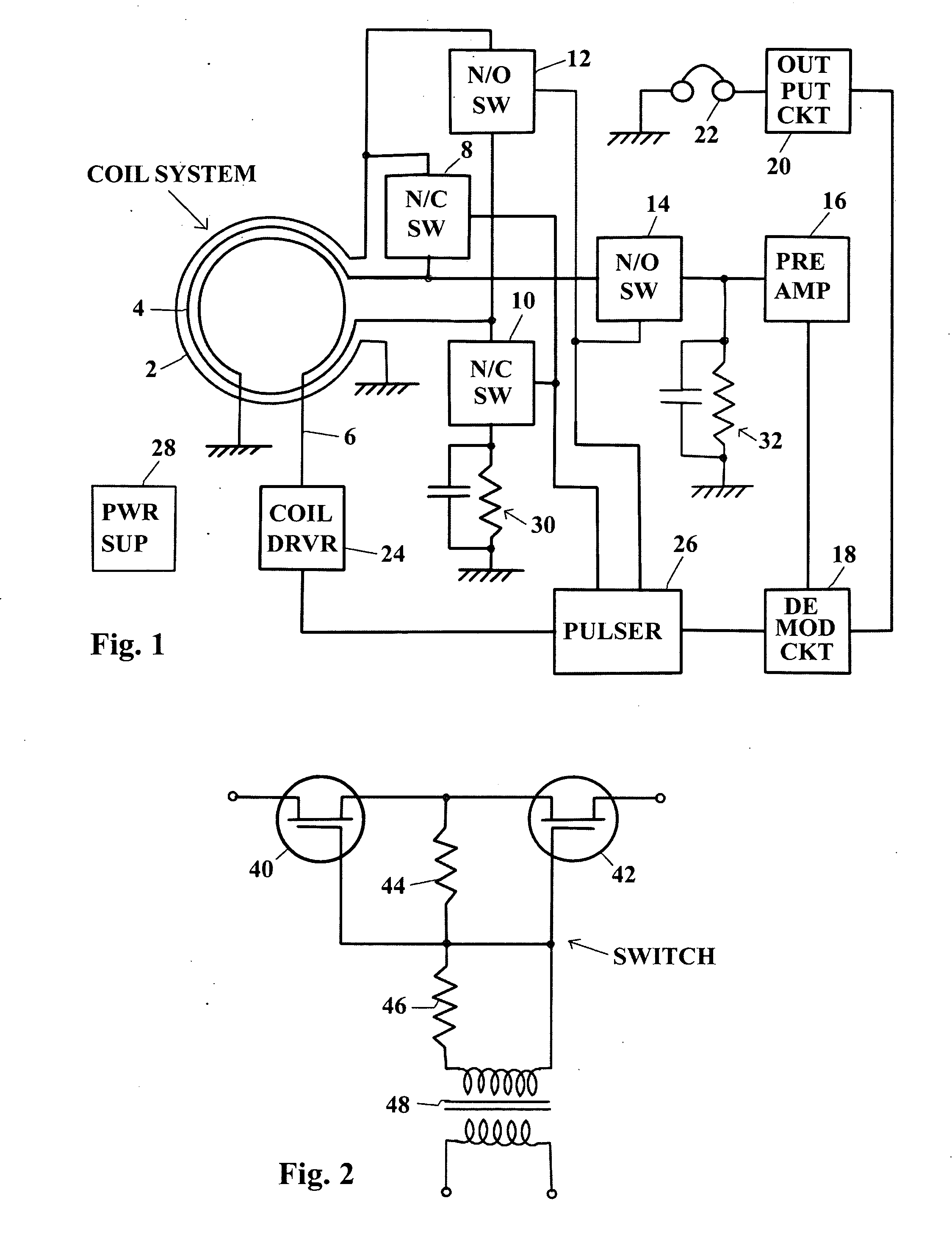
[0020]FIG. 1 shows a block diagram of the preferred embodiment of the invention.

[0021] The receiver coil consists of windings 2 and 4, which are wound in a bifilar arrangement. Windings 2 and 4 are also twisted around each other, to minimize coupling to adjacent windings. For maximal effect, the pitch of the twist should exceed two turns per inch.

[0022] Switches 8, 10, 12 and 14 are floating with respect to ground and have an on-resistance less than 100 ohms. They may be implemented with circuits shown in FIG. 2

[0023] Preamplifier 16, demodulator 18, and output circuit 20 may be implemented with conventional circuits, familiar to those skilled in the art.

[0024] Human interface device 22 generates an auditory signal to alert the operator, but it may also provide visual or tactile indicia.

[0025] Power supply 28 converts the voltage from the power line or a battery to voltages appropriate for the operation of the circuit. The design of the power supply is conventional, using switch...


PUM


Abstract

A pulse-induction-type metal detector in which the receiver coil comprises bifilar windings that are connected in series, opposing during the coil pulse and in series, aiding, following the coil pulse. Pick-up of energy by the receiver coil during the coil pulse is thereby minimized and the duration of oscillations is curtailed. Owing to the rapid recovery of the system from the flux change that is used to charge the target, the signal sampling gate can be positioned very close to the trailing edge of the coil-current pulse, whereby detection of targets with very short time constants is made possible.

Description

CROSS-REFERENCE TO RELATED APPLICATIONS [0001] Provisional Application No. 60 / 646921, filed on Jan. 24, 2005.BACKGROUND OF THE INVENTION [0002] This invention relates to metal detectors, and specifically to receiver coils used in pulse-induction-type metal detectors. [0003] In such detectors, a primary magnetic flux pulse is directed into the medium to be searched, and a secondary flux is generated by eddy-currents in the target. The voltage induced by the secondary flux is sensed by a receiver coil. [0004] The primary flux also induces a voltage in the receiver coil, and the target voltage cannot be effectively detected until the effects of the primary flux have substantially subsided. [0005] The energy absorbed by the receiver coil is not dissipated immediately after the cessation of the coil pulse. The inductance and self-capacitance of the receiver coil constitute a resonant circuit that oscillates until the absorbed energy is dissipated. Usually a damping circuit is placed acro...

Claims


Application Information

Patent Timeline
IPC IPC(8): G01R27/28
CPCG01V3/107H03K17/6874H03K17/691
Inventor WESTERSTEN, ALLAN
Owner DIENCO
Learn More