
Enhanced chest compressor

a chest compressor and compression tube technology, applied in the field of chest compressors, can solve the problems of additional energy required to move the piston, unsatisfactory, etc., and achieve the effects of avoiding a large downward force, minimizing energy absorbed, and slowing down the piston motion

Active Publication Date: 2014-07-29
SUNLIFE SCI INC
View PDF21 Cites 6 Cited by
  • Summary
  • Abstract
  • Description
  • Claims
  • Application Information

AI Technical Summary

Benefits of technology

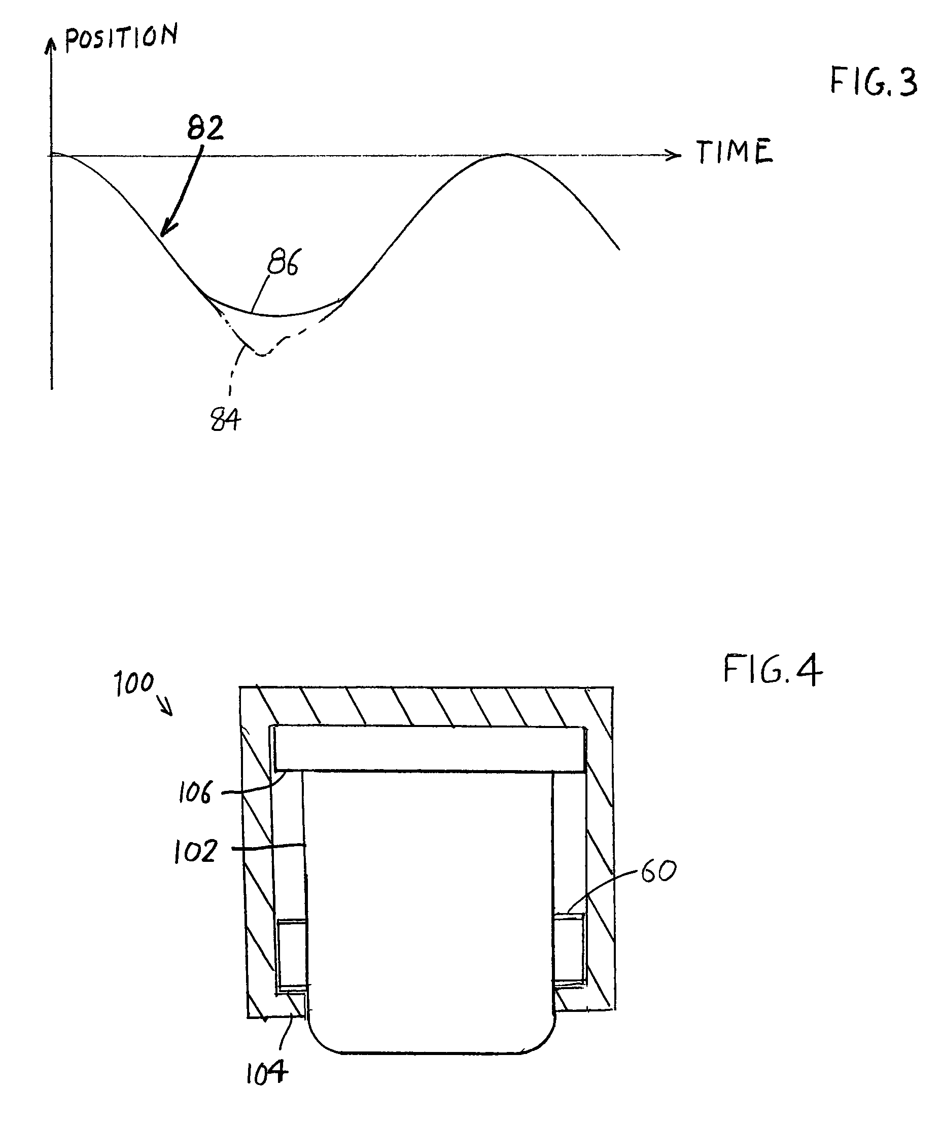
[0004]In accordance with one embodiment of the present invention, a chest compressor is provided of the type that comprises an actuator that includes a piston that moves vertically (when the patient's chest faces upward) to repeatedly compress the patient's chest, wherein piston motion is gradually reversed near the bottom of its downstroke while minimizing the energy absorbed to create such reversal. The piston moves during most of its downstroke without having to overcome the force of a spring that would slow its downward motion. A spring, such as a wave spring, first engages the piston near the bottom of its downstroke and at that time the spring rapidly slows downward motion of the piston and avoids a large downward force at the end of the stroke.

Problems solved by technology

A rapidly downwardly-moving piston tends to impart a downward pulse to the patient at the bottom of the stroke, which is not desirable.
However, the spring force applied along most of the piston movement tends to slow piston movement so additional energy is required to move the piston.

Method used


Image

  • Enhanced chest compressor
  • Enhanced chest compressor
  • Enhanced chest compressor

Examples


Embodiment Construction

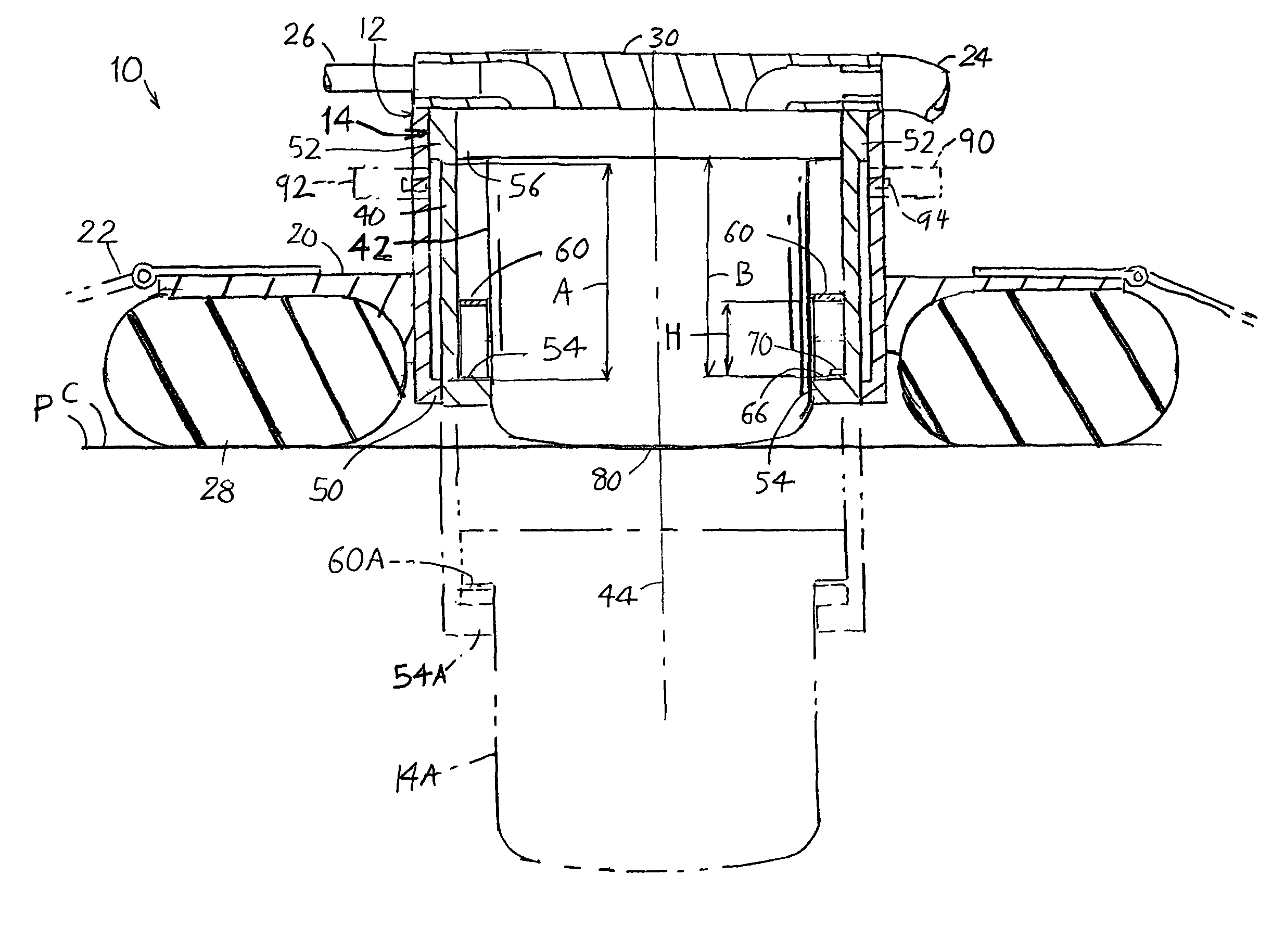
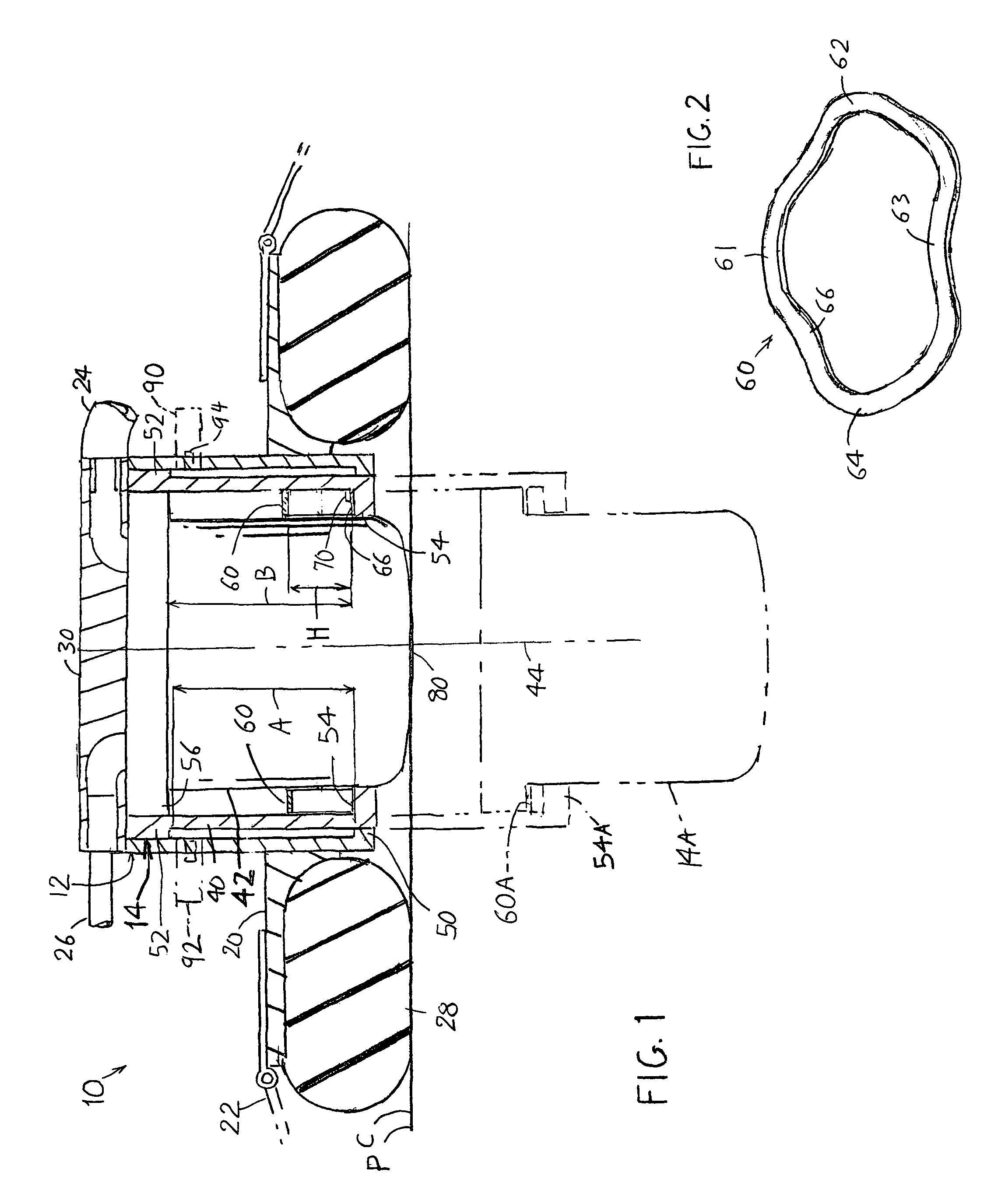
[0011]FIG. 1 illustrates a chest compressor 10 mounted on a patient P to repeatedly compress the patient's chest C. The chest compressor includes a cylinder 12 (which is not necessarily cylindrical) whose function is to guide a piston 14 in vertical movement. In the following discussion it is assumed that the patient lies in a reclined position with his / her chest facing upward. A frame 20 is attached to the cylinder and it holds a strap 22 that encircles the patient's upper torso and holds a stabilizer 28 that resists tipping. The piston repeatedly moves from an upward position shown at 14 to a downward position shown at 14A, at a rate such as a stroke every ½ to one second.

[0012]In the chest compressor illustrated, the piston 14 is moved downward by compressed fluid such as compressed air or oxygen that flows through a control into the cylinder though a tube 24 and out though another tube 26, both tubes being connected to a top plate 30 of the cylinder. Applicant finds that suffici...


PUM


Abstract

A chest compressor includes a piston (14) that moves in downward and upward strokes, with the piston undergoing a smooth reversal at the bottom of the downward stroke. A compression spring such as a wave spring (60), is positioned to engage the piston only near the end of its downward stroke, to smoothly reverse the piston motion, limit downward force on the patient at the end of the stroke, and avoid a downward pulse due to the momentum of the downwardly-moving piston. A stop (90, 92) is latchable in an inward position to allow reduction in the piston stroke by engaging an outward flange (56) on the piston before the piston has moved fully downward.

Description

BACKGROUND OF THE INVENTION[0001]An automatic chess compressor can be carried by an emergency worker and applied to a patient to stimulate blood circulation and breathing. Such a chest compressor usually includes a piston that moves up and down in a cylinder (assuming that the patient is reclined so his chest faces upward). The cylinder is held closely over the patient's chest as by a strap wrapped around the patient's chest area. The chest compressions may occur at a frequency such as ½ to one second apart, so the piston moves downward rapidly in each stroke.[0002]A rapidly downwardly-moving piston tends to impart a downward pulse to the patient at the bottom of the stroke, which is not desirable. It is possible to use a spring that is fixed to the piston to reduce the downward force as the piston moves down. However, the spring force applied along most of the piston movement tends to slow piston movement so additional energy is required to move the piston. A spring has the advanta...

Claims


Application Information

Patent Timeline
Patent Type & Authority Patents(United States)
IPC IPC(8): A61H31/00
CPCA61H31/00A61H31/006A61H2201/018A61H2201/1238A61H2201/1246
Inventor BISERA, JOEWEIL, MAX HARRYTANG, WANCHUNCASTILLO, CARLOS
Owner SUNLIFE SCI INC
Learn More