Hinge structure

a technology of hinge structure and hinges, which is applied in the direction of collapsible antenna means, wing accessories, manufacturing tools, etc., can solve the problem of inflexible installation

Inactive Publication Date: 2006-08-03
SMARTANT TELECOMM
View PDF12 Cites 11 Cited by
  • Summary
  • Abstract
  • Description
  • Claims
  • Application Information

AI Technical Summary

Benefits of technology

[0013] When the body and the cover are coupled, the second anchor ring is deformed due to the deformation slot and is inserted into the second pivot hole and the first pivot hole, and latched on the anchor end of the first pivot hole. The anchor member is inserted into the anchor hole to be in contact with the first coupling section. The first anchor ring is coupled with the second pivot hole. The brake member and the wall of the first pivot generate a frictional force to enable the cover to be turned relative to the body and anchored at any angle desired. Hence the directional plate may be adjusted and moved to a desired position in the Z axis, to accurately align with the location of the wireless server, to enhance the gain of signal concentration, and facilitate radio signal transmission and receiving.
[0014] The body has a hanging hole on the bottom so that the entire directional antenna may be hung on a wall. Moreover, the body has a magnetic element to enable the entire hinge structure to be attracted to a metal material, such as a metal partition. Such a design can enhance the installation flexibility of the hinge structure.

Problems solved by technology

As the conventional antenna adopted the universal joint limits the antenna to swivel relative to the base dock only on a plane formed by X-Y axes, and may be positioned only on a horizontal platform and cannot be hung on a wall or mounted onto a metal partition, installation is inflexible.

Method used


Image

  • Hinge structure
  • Hinge structure
  • Hinge structure

Examples


Embodiment Construction

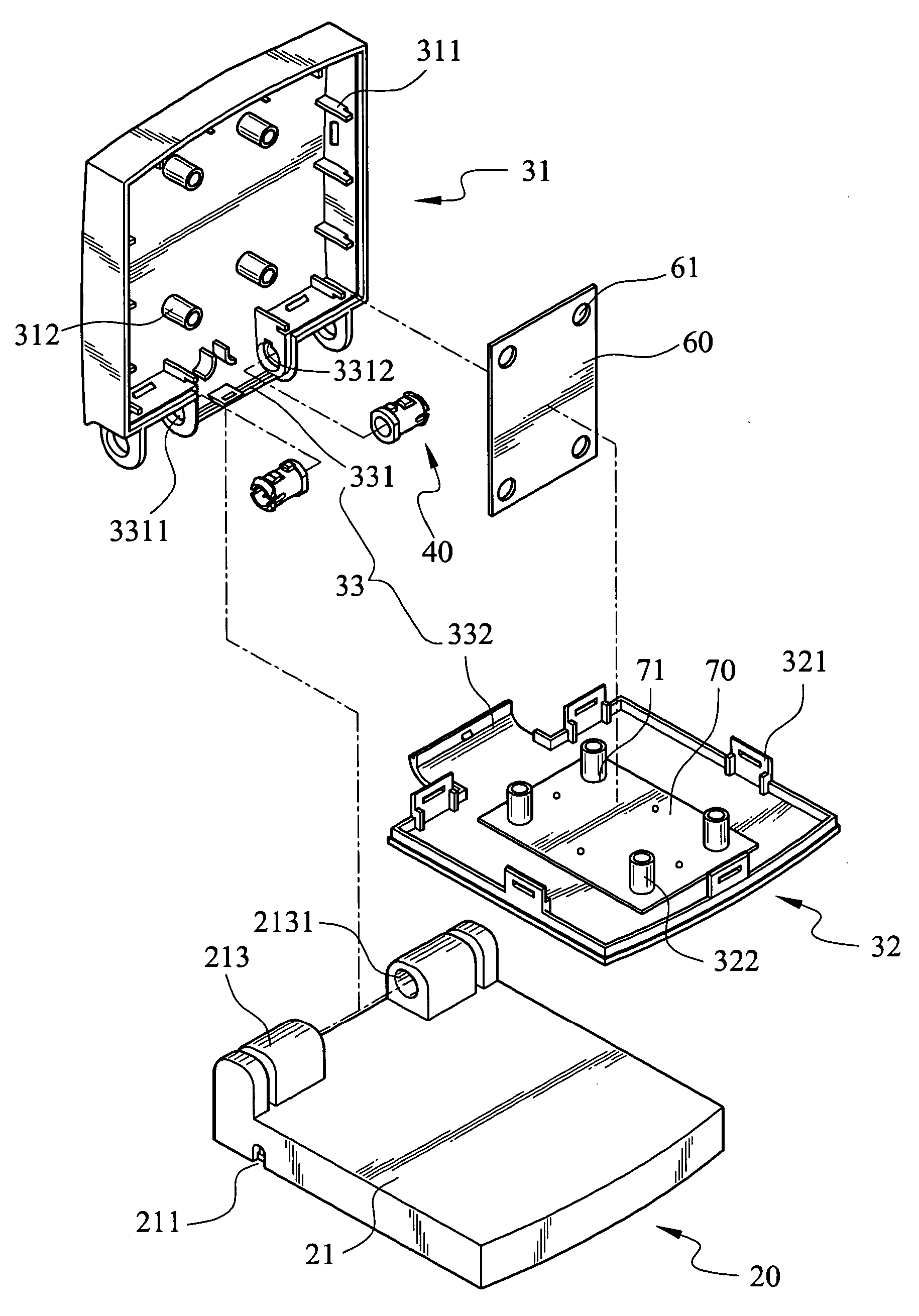
[0023] The hinge structure according to the invention mainly is adopted for use on a directional antenna to pivotally couple a directional plate on one side of a base dock, and enable the directional plate to be swiveled relative to the base dock. However, the hinge structure of the invention also can be used on other mechanisms or electronic devices that have a cover to be opened and closed relative to a body, such as a flipping mobile phone, palm size computer, P DA, and the like. The following discussion is based on an embodiment of the directional antenna.

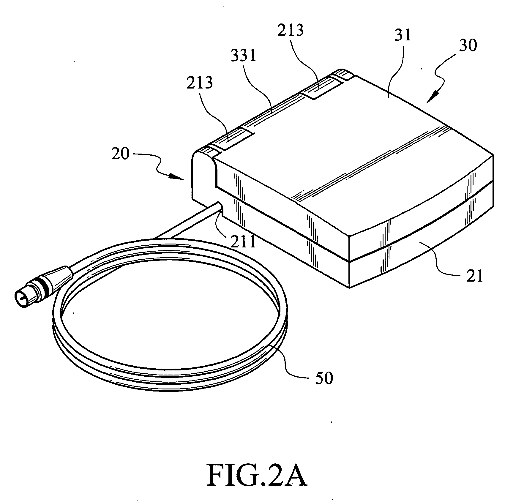
[0024] Refer to 2A and 2B for a perspective view and an exploded view of the hinge structure of the invention, FIGS. 3A and 3B for a perspective view and an exploded view of the body of the hinge structure, FIGS. 4A and 4B for a perspective view and an exploded view of the cover of the hinge structure, FIGS. 4C and 4D for a bottom view of an upper cap and a perspective view of a lower cap, FIG. 5 for a perspective view of the ...


PUM


Abstract

A hinge structure is disclosed. Each of a pair of axles is inserted into a first pivot hole of the body through a second pivot hole of the cover, to enable the cover to be swiveled about the axle relative to the body. When the body and the cover are coupled together, a second anchor ring of the axle is deformed through a deformation slot of the axle and is inserted into the second pivot hole and the first pivot hole and latched on one end of the first pivot hole. A first anchor ring of the axle is latched in the second pivot hole on another end of the first pivot hole. A movable brake member of the axle and the wall of the first pivot hole generate a frictional force to enable the cover to be swiveled relative to the body and anchored at any angle desired.

Description

FIELD OF THE INVENTION [0001] The present invention relates to a hinge structure and particularly to a hinge structure for use on a directional antenna to enable a directional plate to swivel relative to a base dock. BACKGROUND OF THE INVENTION [0002] With the rapid advance of electronic technology, desktop computers or notebook computers now have powerful functions and are widely used by companies, enterprises and consumers. In order to effectively link those computers to transmit or exchange information and data, most companies or enterprises have installed signal cables and servers to set up required internal networks. As design and actual wiring of the fixed line network is expensive, and construction and wiring of the fixed line network often result in damage of the building, it is a severe problem, especially for the company, which rents or leases offices. Moreover, the entangled wiring also is difficult to manage and maintain. Hence these days many companies or enterprises us...

Claims


Application Information

Patent Timeline
Patent Type & Authority Applications(United States)
IPC IPC(8): E05D11/08
CPCE05D7/1055E05D11/082E05Y2900/606Y10T16/54038H01Q1/1207H01Q3/06H01Q1/084
Inventor CHIANG, TENG-CHAOYANG, SHENG-HSUNG
Owner SMARTANT TELECOMM
Why Eureka
Try Eureka