Concealed automatic pool vacuum systems

a vacuum system and vacuum hose technology, applied in the direction of thin material handling, construction, building types, etc., can solve the problems of uncoiled labor-intensive and time-consuming, and at best haphazard storage of vacuum hoses

Inactive Publication Date: 2006-08-03
TORKELSON JOHN E
View PDF20 Cites 90 Cited by
  • Summary
  • Abstract
  • Description
  • Claims
  • Application Information

AI Technical Summary

Benefits of technology

[0011] In accordance with a preferred embodiment hereof, this invention provides a system related to the uncoiled storage of at least one vacuum hose of at least one automatic pool cleaner within at least one pool of water, the at least one vacuum hose comprising at least one first hose end and at least one second hose end, the at least one pool of water comprising at least one low-pressure fluid sourc

Problems solved by technology

This is very labor-intensive and time-consuming.
Some manufacturers of pool cleaning heads specifically void the operational warranty of the device if the vacuum hose is stored in a coiled configuration.
Current

Method used


Image

  • Concealed automatic pool vacuum systems
  • Concealed automatic pool vacuum systems
  • Concealed automatic pool vacuum systems

Examples


Embodiment Construction

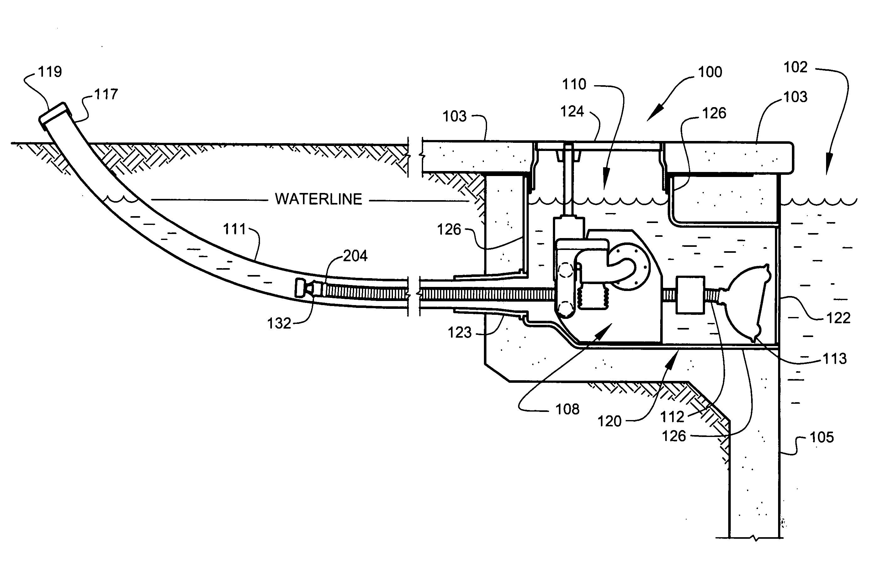
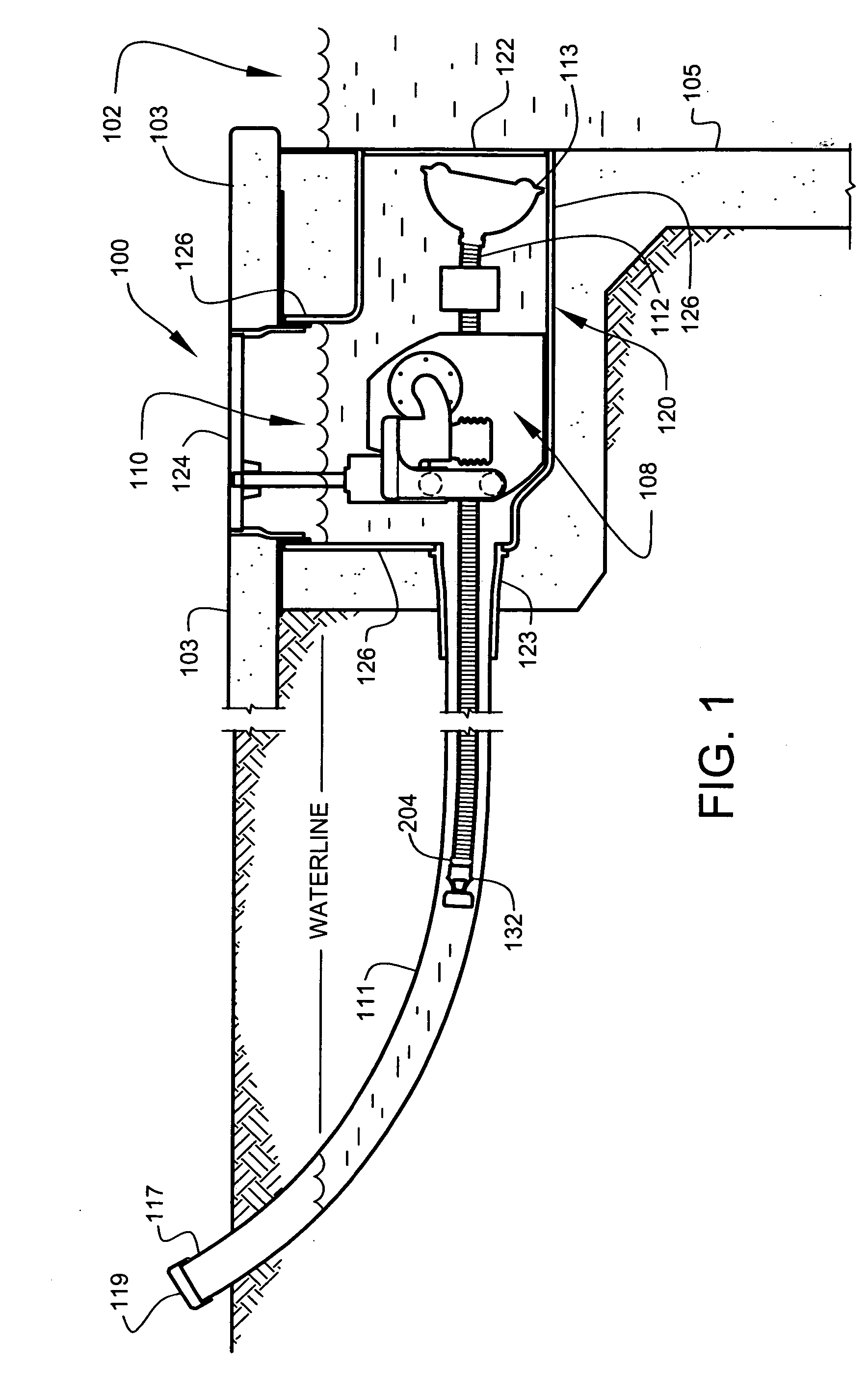
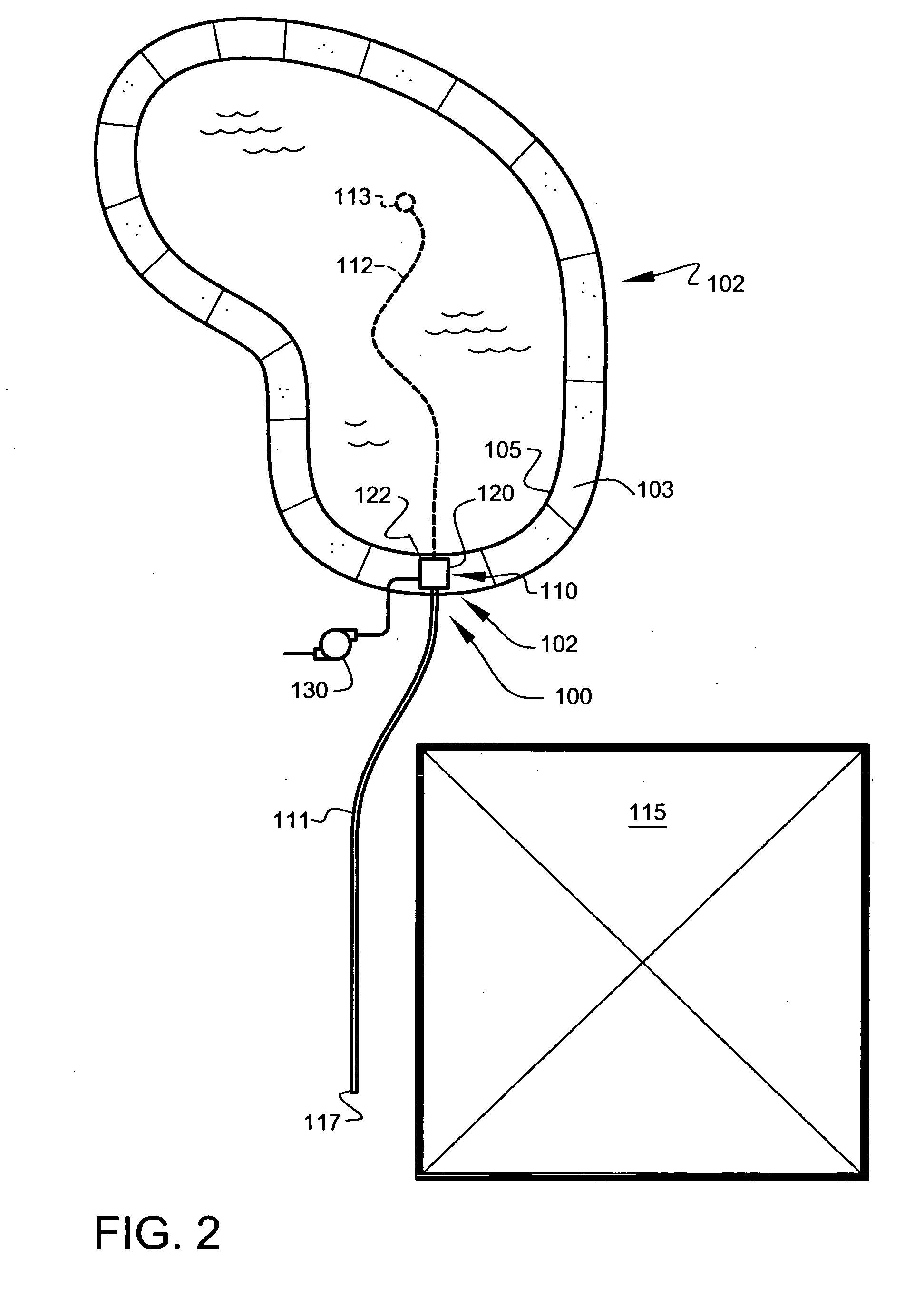
[0076]FIG. 1 shows a side view, in partial section, of automatic vacuum assembly 110 of pool-cleaning system 100, retracted into pool-wall housing 120, according to a preferred embodiment of the present invention. FIG. 2 shows a plan view of a water-filled swimming pool 102 incorporating pool-cleaning system 100 of FIG. 1.

[0077] In the following specification, the terms “suction” and “vacuum” are used interchangeably to define conditions of decreased fluid pressure within the fluid (water) transporting interstices of pool-cleaning system 100 (generally associated with plumbing assemblies on the “suction side” (low-pressure side) of a water circulation pump). In the present disclosure, “suction side” refers to the pipes and fittings that draw water out of swimming pool 102 to be filtered

[0078] Preferably, pool-cleaning system 100 comprises an automatic vacuum-cleaning system that automatically deploys swimming pool vacuum hose 112 with an attached pool vacuum head 113, to clean the...


PUM


Abstract

A vacuum pool-cleaning storage system that is housed in the side of a swimming pool substantially below the waterline. The pool vacuum cleaner automatically deploys to clean the pool when the central pool vacuum pump is activated, and automatically retracts to a stored position when the central pool vacuum pump is turned off. The system is adapted to store the vacuum hose in a substantially linear tube located substantially underground. A reel-type hose storage embodiment is also disclosed. The system is preferably powered by vacuum pressure generated by a water circulation pump of the pool plumbing system.

Description

CROSS-REFERENCE TO RELATED APPLICATIONS [0001] The present application is a continuation-in-part of related application Ser. No. 11 / 001,557, filed Nov. 30, 2004, entitled “POOL CLEANING SYSTEMS”, and is related to and claims priority from prior provisional application Ser. No. 60 / 528,771 filed Dec. 12, 2003 entitled “SWIMMING POOL VACUUM AND HOSE AUTOMATIC DEPLOYMENT AND RETRIEVAL GARAGE”, and is further related to and claims priority from prior provisional application Ser. No. 60 / 641,607 filed Jan. 6, 2005, entitled “SWIMMING POOL VACUUM HOSE AUTOMATIC DEPLOYMENT AND RETRIEVAL GARAGE WITH SEMI STRAIGHT HOSE STORAGE” the contents of which are incorporated herein by this reference and are not admitted to be prior art with respect to the present invention by the mention in this cross-reference section.BACKGROUND [0002] This invention relates to providing pool-cleaning systems. More particularly, this invention relates to providing a system for improved storage and deployment of pool v...

Claims


Application Information

Patent Timeline
IPC IPC(8): B65H75/34
CPCB65H75/36B65H75/4402B65H75/4489B65H2701/33E04H4/1654E04H4/1681Y10T137/6932E04H4/1645E04H4/1672
Inventor TORKELSON, JOHN E.
Owner TORKELSON JOHN E
Why Eureka
Try Eureka