
Internally damped laminated tube

a laminated metal tube, internal damped technology, applied in the direction of pipes, pipe elements, mechanical equipment, etc., can solve the problems of increasing the complexity, cost and weight of the main tube, and the noise and vibration in the tubes, so as to achieve the effect of reducing noise and vibration

Inactive Publication Date: 2006-08-03
MATERIAL SCIENCES CORPORATION
View PDF21 Cites 14 Cited by
  • Summary
  • Abstract
  • Description
  • Claims
  • Application Information

AI Technical Summary

Benefits of technology

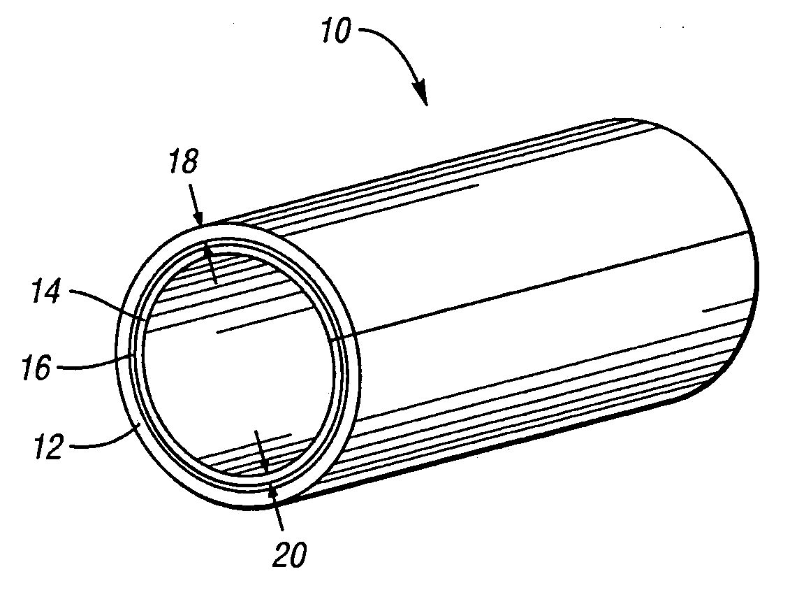
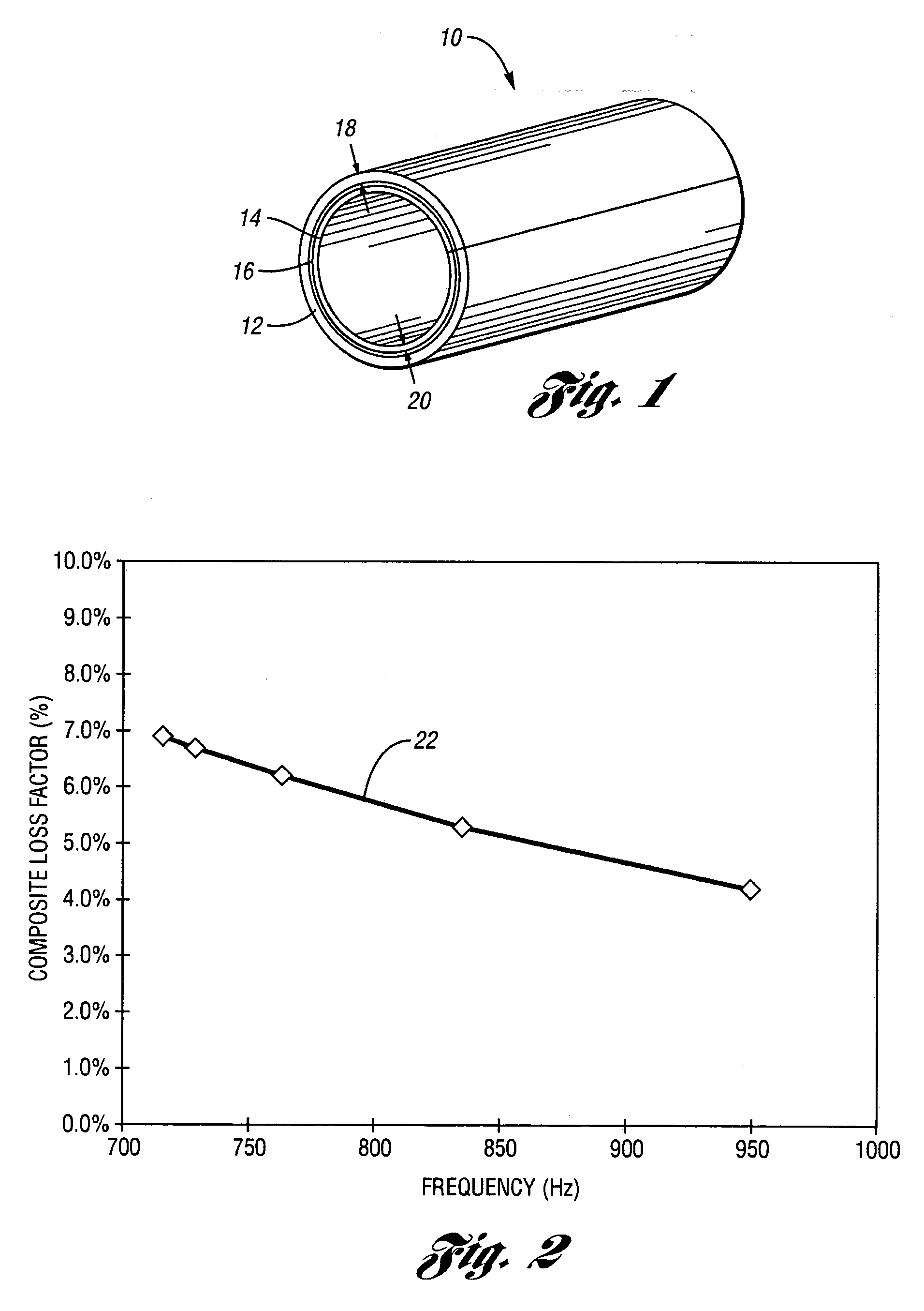
[0004] Accordingly, the present invention provides an internally damped laminated tube comprising an outer layer and an inner layer, with a viscoelastic layer disposed therebetween. The outer and inner layers constrain the viscoelastic layer, thereby providing noise and vibration reduction through constrained-layer damping. The outer layer has a first thickness, while the inner layer has a second thickness less than the first thickness. Preferably, the first thickness is at least two times the second thickness. While both the outer and inner layers act as constraining layers, the outer layer also preferably provides structural support for the tube, thus necessitating a thicker outer layer. Preferably, the outer and inner layers comprise steel. The internally damped tube according to the present invention exhibits a composite loss factor greater than four percent for ring modes occurring at vibrational frequencies between 700 and 950 Hz.

Problems solved by technology

At various resonances, the dynamic loads cause excess noise and vibration in the tubes.
Each of the resonance reducing structures described above increases the complexity, cost and weight of the main tube.

Method used


Image

  • Internally damped laminated tube
  • Internally damped laminated tube

Examples


Embodiment Construction

[0008] Referring to FIG. 1, an internally damped laminated tube according to the present invention is shown at 10. The tube 10 has an outer layer 12 and an inner layer 14, with a viscoelastic layer 16 disposed therebetween to provide internal damping as described herein. Preferably, the outer and inner layers 12, 14 are formed from steel. However, any material may be used to form the outer and inner layers 12, 14 without changing the inventive concept, with the material chosen dependent upon the structural properties necessary for the intended application. The viscoelastic layer 16 is a viscoelastic material as known in the art. Any viscoelastic material may be used for the viscoelastic layer 16, with the viscoelastic material chosen dependent upon the intended application.

[0009] Sandwiching the viscoelastic layer 16 between the outer and inner layers 12, 14 provides noise and vibration reduction from within the tube 10, thereby eliminating the need for additional parts or material...


PUM


Abstract

An internally damped laminated tube comprises an outer layer and an inner layer, with a viscoelastic layer disposed therebetween. The outer and inner layers constrain the viscoelastic layer, thereby providing noise and vibration reduction through constrained-layer damping. While both the outer and inner layers act as constraining layers, the outer layer also preferably provides structural support for the tube, thus necessitating a thicker outer layer. Preferably, the outer and inner layers comprise steel. The internally damped tube according to the present invention exhibits a composite loss factor greater than four percent for ring modes occurring at vibrational frequencies between 700 and 950 Hz.

Description

TECHNICAL FIELD [0001] The present invention relates to an internally damped laminated metal tube designed for noise reduction and vibration damping. BACKGROUND OF THE INVENTION [0002] Metal tubes are often used in applications where dynamic loads are applied to the tubes. At various resonances, the dynamic loads cause excess noise and vibration in the tubes. Much effort has been exerted to reduce or eliminate the negative effects of tube resonances. Tube resonances include the “bending” and “torsion” resonances of the tube, as well as the “ring” modes or “shell” modes of the tube, the latter occurring at higher frequencies and smaller wavelengths than the bending and torsion modes. [0003] Traditionally, parts or materials are added to a main tube to reduce the tube resonances. For example, internal vibration absorbers generally comprise a cardboard tube inserted within the main tube to provide frictional damping. The cardboard tube provides low levels of frictional damping of high ...

Claims


Application Information

Patent Timeline
Patent Type & Authority Applications(United States)
IPC IPC(8): F16L55/04
CPCF16L55/0336F16L9/21
Inventor GOETCHIUS, GREGORY M.SCHWAEGLER, JAMES R.
Owner MATERIAL SCIENCES CORPORATION
Learn More