Auto-injector storage and dispensing unit

Active Publication Date: 2006-08-03
MYLAN
View PDF21 Cites 37 Cited by
  • Summary
  • Abstract
  • Description
  • Claims
  • Application Information

AI Technical Summary

Benefits of technology

[0012] The subject invention is directed to a surface-mountable storage system for an auto-injection device, the system having fixed location and being capable of alternately enclosing an auto-injection device or presenting the device for removal. Such a storage system protects the device from damage or accidental use and maintains such

Problems solved by technology

Because these and other sources of allergy are prevalent in everyday life, one who is allergic to such a substance cannot predict when they may come in contact with it and have an allergic reaction.
When reactions do occur, they can be severe (a condition called “anaphylaxis”); without immediate treatment, anaphylaxis is potentially life-threatening.
There are several difficulties associated with the process of constantly carrying an auto-injection device.
First, because auto-injection devices include an injection needle and various movable parts, they are relatively fragile and in need of protection from mechanical forces.
Second, users must guard against exposing epinephrine to temperature extremes, which can cause it to deteriorate.
Third, constantly carrying epinephrine can increase its exposure to UV light, to which it is sensitive.
Specifically, epinephrine will oxidize under UV light, turning brown in the process and becoming ineffective.
While the prior art protective cases for auto-injection devices, as illustrated by Odom and Penney, have alleviated some of the problems associated with the process of constantly carrying such a device, other difficulties persist.
For example, because the prior art protective cases are relatively small and meant to travel with the device, they can be easily misplaced.
In places visited regularly, such as a home or office, such cases are often stored out of view, in pockets or drawers, making them easily forgotten when traveling and difficult to locate in times of urgent need.
This latter issue is highlighted in si

Method used


Image

  • Auto-injector storage and dispensing unit
  • Auto-injector storage and dispensing unit
  • Auto-injector storage and dispensing unit

Examples


Embodiment Construction

[0026] The present invention overcomes many of the prior art problems associated with storing auto-injection devices in preparedness for use. The advantages, and other features of the system disclosed herein, will become more readily apparent to those having ordinary skill in the art from the following detailed description of certain preferred embodiments taken in conjunction with the drawings which set forth representative embodiments of the present invention and wherein like reference numerals identify similar structural elements.

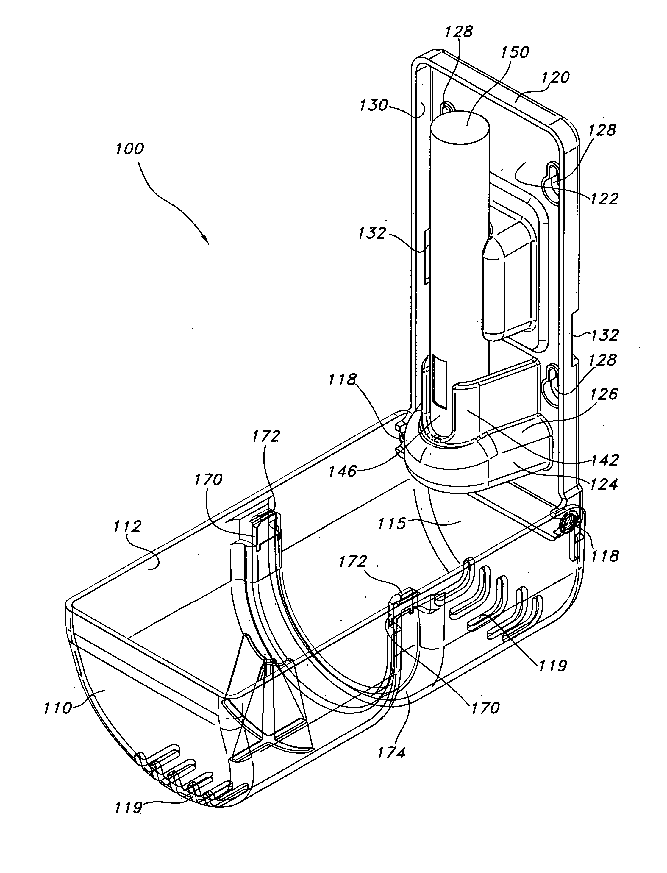
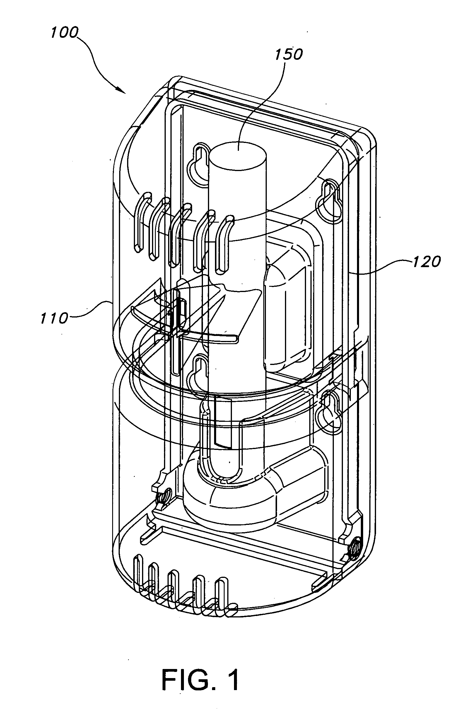
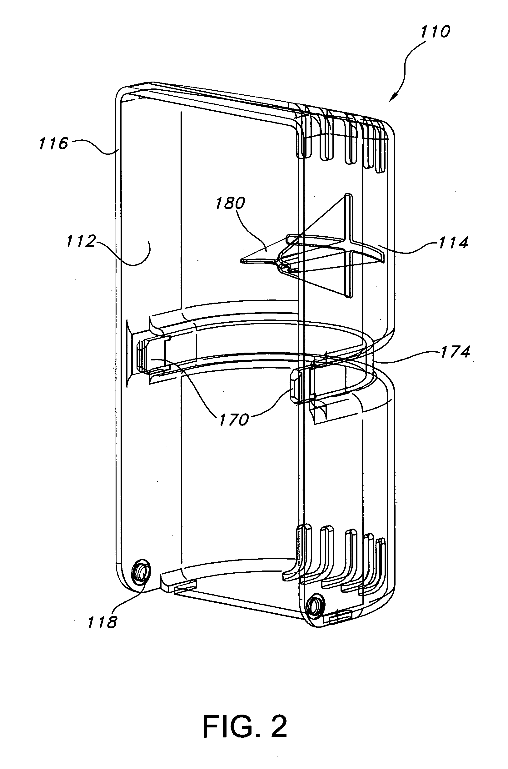
[0027] Referring to FIGS. 1 and 2, there is illustrated a preferred embodiment of an auto-injector storage and dispensing unit (a “storage unit”) that is the subject of the present disclosure, the storage unit generally indicated by reference numeral 100. The storage unit 100 has a cover 110 attached to a base 120 in a manner that allows the cover 110 to move with respect to the base 120 (the nature of the attachment and movement is discussed in more det...


PUM

PropertyMeasurementUnit
Forceaaaaaaaaaa
Pressureaaaaaaaaaa
Flow rateaaaaaaaaaa

Abstract

The subject invention is directed to a surface-mountable storage system for an auto-injection device. The storage system includes a base and a cover. The base has a back surface adapted to be mounted to a generally vertical surface. A support structure secured to the base releasably holds an auto-injection device on end and adjacent the front surface. The cover has a free edge adapted to be substantially continuously adjacent the base. This allows the cover and base to substantially enclose the auto-injection device when the cover is in a closed position with respect to the base. The storage system also has means for securing the cover to the base to allow the cover to move between the closed position and an open position that presents the auto-injection device for removal from the releasable holding means.

Description

BACKGROUND OF THE INVENTION [0001] 1. Field of the Invention [0002] The subject disclosure relates to storage systems for auto-injection devices, and more particularly to storage systems having fixed locations and capable of dispensing auto-injection devices. [0003] 2. Background of the Related Art [0004] Many individuals are highly allergic to commonly encountered substances. Examples of common substances which are also common allergens include peanuts, milk, shellfish, latex, and venom from bee stings. Because these and other sources of allergy are prevalent in everyday life, one who is allergic to such a substance cannot predict when they may come in contact with it and have an allergic reaction. When reactions do occur, they can be severe (a condition called “anaphylaxis”); without immediate treatment, anaphylaxis is potentially life-threatening. As a result, many people with known allergies must be continuously ready to treat a reaction. [0005] In order to treat anaphylaxis, ma...

Claims


Application Information

Patent Timeline
IPC IPC(8): B65D83/10
CPCA61M5/002
Inventor PRINDLE, MICHAEL
Owner MYLAN
Why Eureka
Try Eureka