Antenna system for remote control automotive application

a technology for remote control and automotive applications, applied in the direction of antennas, antenna supports/mountings, antenna adaptation in movable bodies, etc., can solve the problems of increasing the number of antennas, reducing the antenna gain, and reducing so as to reduce the number of null regions

Inactive Publication Date: 2006-08-03
TENATRONICS
View PDF10 Cites 48 Cited by
  • Summary
  • Abstract
  • Description
  • Claims
  • Application Information

AI Technical Summary

Benefits of technology

[0007] In accordance with one aspect of the present exemplary embodiment, an antenna system for remote control applications comprises a communications module; an antenna assembly; and a radio frequency cable, having a first connection end and a second connection end, wherein the first connection end is coupled to the communications module and the second connection end is coupled to the antenna assembly. The antenna assembly is located a predetermined distance from the communications module, the predetermined distance substantially reducing null regions in an antenna radiation pattern of the antenna system.

Problems solved by technology

This increased wiring and associated equipment makes it difficult to arrange the existing sensor and control electronics within a limited amount of packaging room available in a vehicle.
However, as antenna size decreases, antenna gain decreases, making it more difficult to receive signals.
Moreover, antennas and their corresponding wireless circuitry are sensitive to noise, especially noise generated in close proximity to the antenna.
Devices with internal integrated antennas therefore cannot provide extended communication range because of reduced antenna size and the electromagnetic interference between the antenna and the electronic components of the sensor and control circuits.
While this configuration improves performance, the size of the dipole at 315 MHz is so large that it cannot be contained within the interior parts of the vehicle, e.g. within the vehicle integrated front panel.
Indeed, the size of the dipole restricts the location of the antenna to the inside window of the vehicle.
While the size of the antenna is smaller in this configuration, the system has reduced communication range for some angle directions because of car body shadows.
The metal pillars of the vehicle chassis interfere with the antenna radiation pattern, causing reception nulls in some directions surrounding the vehicle.

Method used


Image

  • Antenna system for remote control automotive application
  • Antenna system for remote control automotive application
  • Antenna system for remote control automotive application

Examples


Embodiment Construction

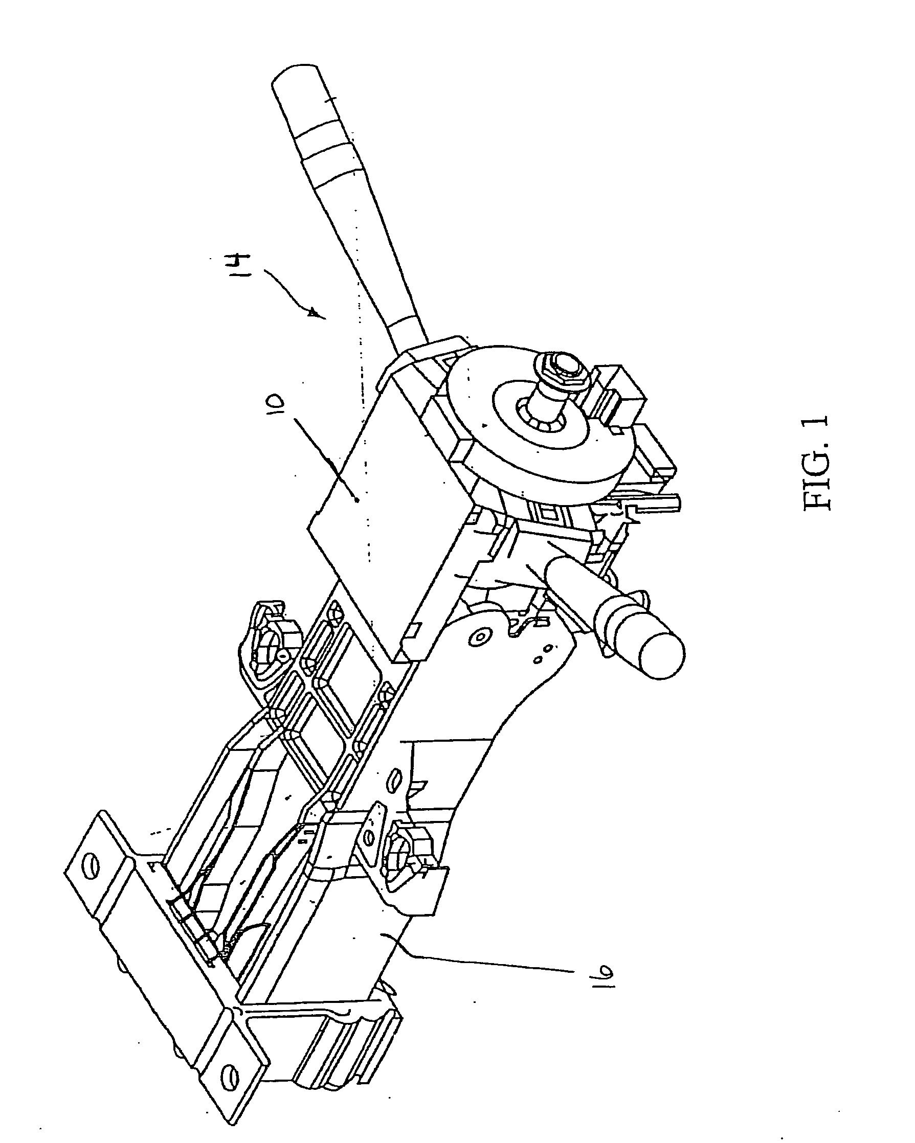
[0024] With reference to FIG. 1, shown is a vehicle steering assembly such as that described in U.S. Pat. No. 6,731,020 to Burr, which is hereby incorporated by reference in its entirety. Communications module 10 is mounted on top of steering column 14. Communications module 10 is grounded to the vehicle chassis 16.

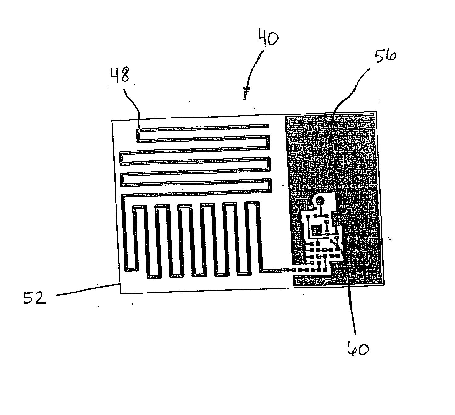
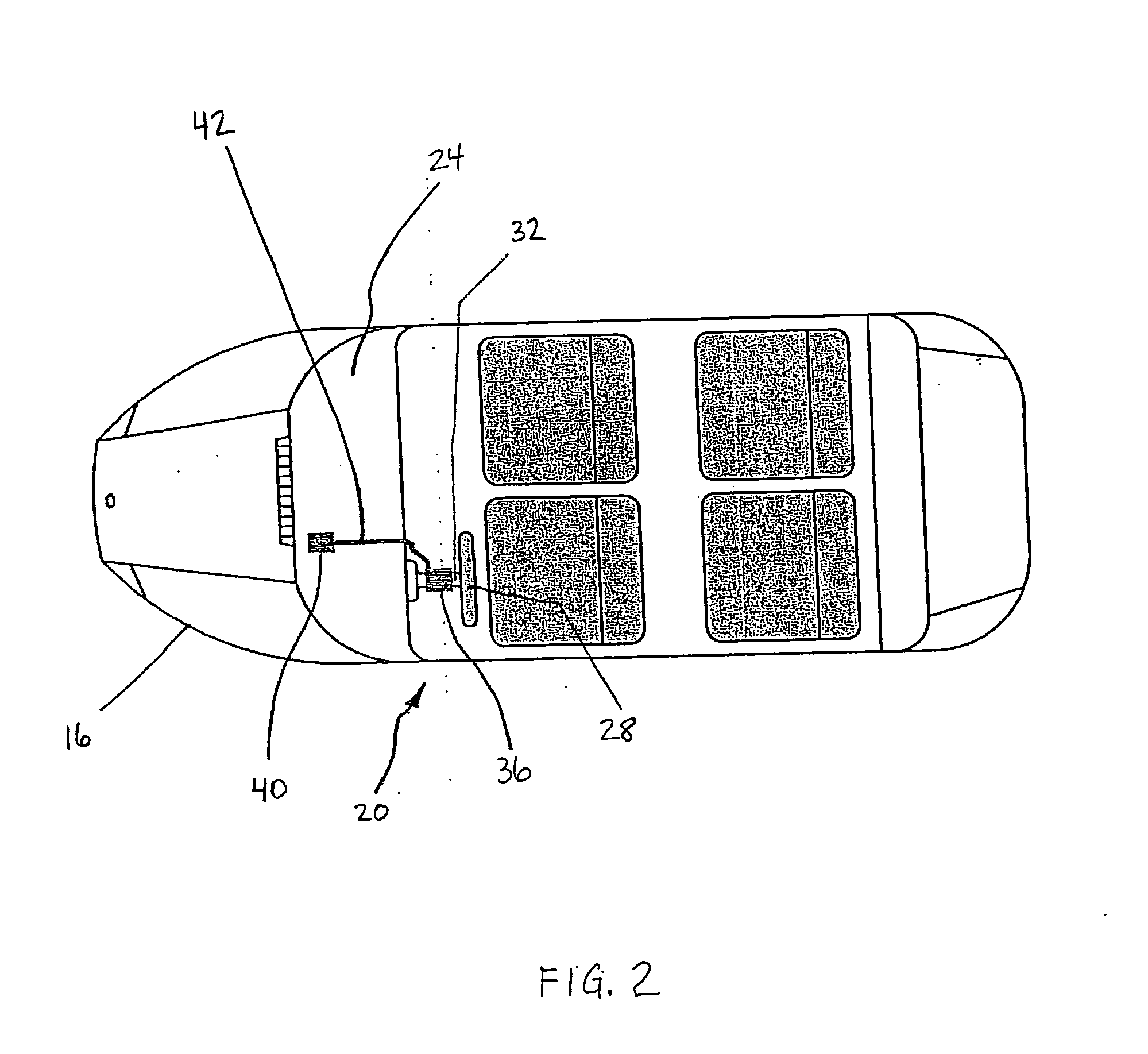
[0025] With reference to FIG. 2, shown is a top view of a typical vehicle implementing one exemplary embodiment of the present concept. Vehicle 20 has a vehicle integrated front panel 24. A steering wheel 28 is mounted on steering column assembly 32. Remote keyless entry (RKE) module 36 is mounted on top of the steering column assembly 32, and is grounded to the vehicle chassis 16. Antenna assembly 40 is separate from the RKE module 36 and is mounted under the vehicle integrated front panel 24. RF cable 42 connects the RKE module 36 to the antenna assembly 40.

[0026] The described assembly commonly operates in a 300 MHz to 500 MHz frequency range. It is to be appreciated...


PUM


Abstract

An antenna system for remote control applications comprises a communications module; an antenna assembly; and a radio frequency cable, having a first connection end and a second connection end, wherein the first connection end is coupled to the communications module and the second connection end is coupled to the antenna assembly. The antenna assembly is located a predetermined distance from the communications module, the predetermined distance substantially eliminating null regions in an antenna radiation pattern of the antenna system. An antenna diversity system for remote control applications comprises an antenna assembly; a communications module; an electronic switch assembly, wherein a first RF cable couples the electronic switch assembly to the antenna assembly and a second RF cable couples the electronic switch assembly to the communications module, wherein the antenna assembly, the first RF cable, the second RF cable, the electronic switch assembly and the communications module form a radio frequency circuit; and a diversity RF cable, coupled to the electronic switch assembly, wherein the electronic switch assembly switches the diversity RF cable into and out of the radio frequency circuit.

Description

CROSS REFERENCE TO RELATED APPLICATION [0001] This application claims the benefit of priority from U.S. Provisional Application No. 60 / 647,885 filed on Jan. 28, 2005, entitled “Antenna System for Remote Control Automotive Application.”BACKGROUND [0002] The present exemplary embodiment relates to a wireless apparatus. It finds particular application in conjunction with remote control operations of an automobile, including remote keyless entry (RKE) automotive communication, and will be described with particular reference thereto. However, it is to be appreciated that the present exemplary embodiment is also amenable to other like applications. [0003] Modern vehicles are operated with more and more optional equipment for providing additional features and achieving more comfort. For example, remote keyless entry (RKE) systems, remote starting devices, and global positioning systems (GPS), etc. have become commonplace amenities. Often, such optional equipment is integrated within an exi...

Claims


Application Information

Patent Timeline
Patent Type & Authority Applications(United States)
IPC IPC(8): H01Q1/36H01Q1/24
CPCH01Q1/243H01Q1/38H01Q5/50H05K1/16H01Q9/40
Inventor RABINOVICH, VICTORREARDON, TERRANCEMIEDEMA, CHRISAL-KHATEEB, BASIMALEXANDROV, NIKOLAI
Owner TENATRONICS
Why Eureka
Try Eureka