Automatic optical inspection using multiple objectives

an optical inspection and objective technology, applied in the field of objects inspection techniques, can solve the problems of high-resolution cameras with high pixel rates, inconvenient operation, and inconvenient maintenance,

Active Publication Date: 2006-08-03
APPL MATERIALS ISRAEL LTD
View PDF4 Cites 16 Cited by
  • Summary
  • Abstract
  • Description
  • Claims
  • Application Information

AI Technical Summary

Benefits of technology

[0010] Another embodiment provides an automated optical inspection system for inspecting article. The system generally includes at least one camera and at least one image scanning module. The image scanning module generally includes a plurality of objective modules with fields of view covering a portion of the article during inspection and an image selection mirror mechanism movable to sequentially transfer images from the fields of view to the camera. For some embodiments, the objective modules in each image scanning module may be arranged in a circle or an arc, allowing a distance between the objective modules and an illumination source to be substantially constant. Arranging the modules in an arc may also allow a single mirror mechanism to be used for each objective module. The image scanning modules may be positioned relative to each other so that the FOVs of the objective modules cover the entire inspected article width with at least some partial overlap.

Problems solved by technology

However, for applications requiring higher throughput, such as web inspection, which may have relatively large surface areas to inspect (e.g., with horizontal dimensions of several feet), a scanning approach may take too much time.
Unfortunately, high resolution cameras with high pixel rates tend to be expensive, often costing many times more than the objectives.
As a result, while systems utilizing multiple image scanning modules may achieve higher throughput than systems that scan with a single module, the cost of multiple high resolutions cameras may render such systems cost prohibitive.

Method used


Image

  • Automatic optical inspection using multiple objectives
  • Automatic optical inspection using multiple objectives
  • Automatic optical inspection using multiple objectives

Examples


Embodiment Construction

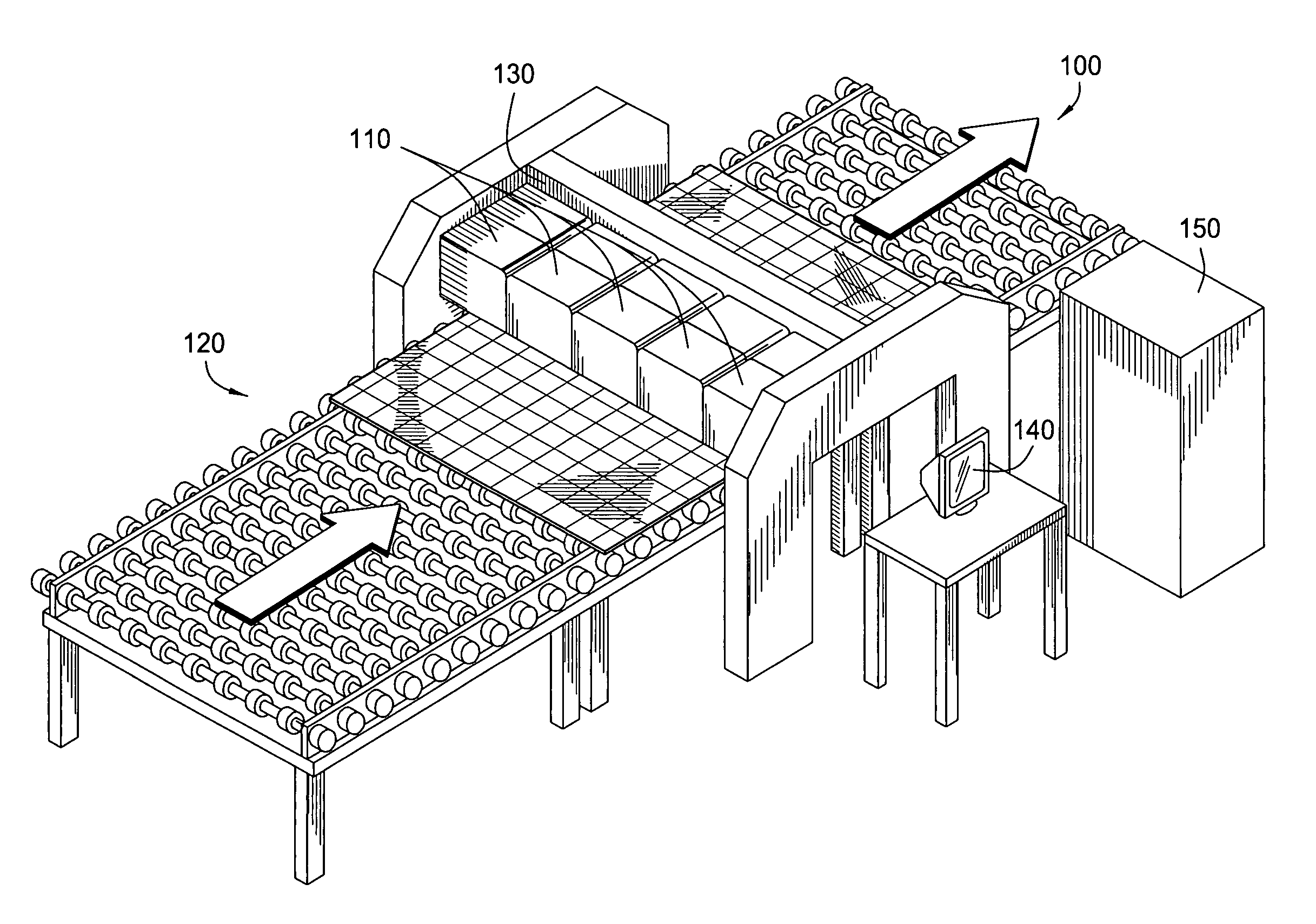
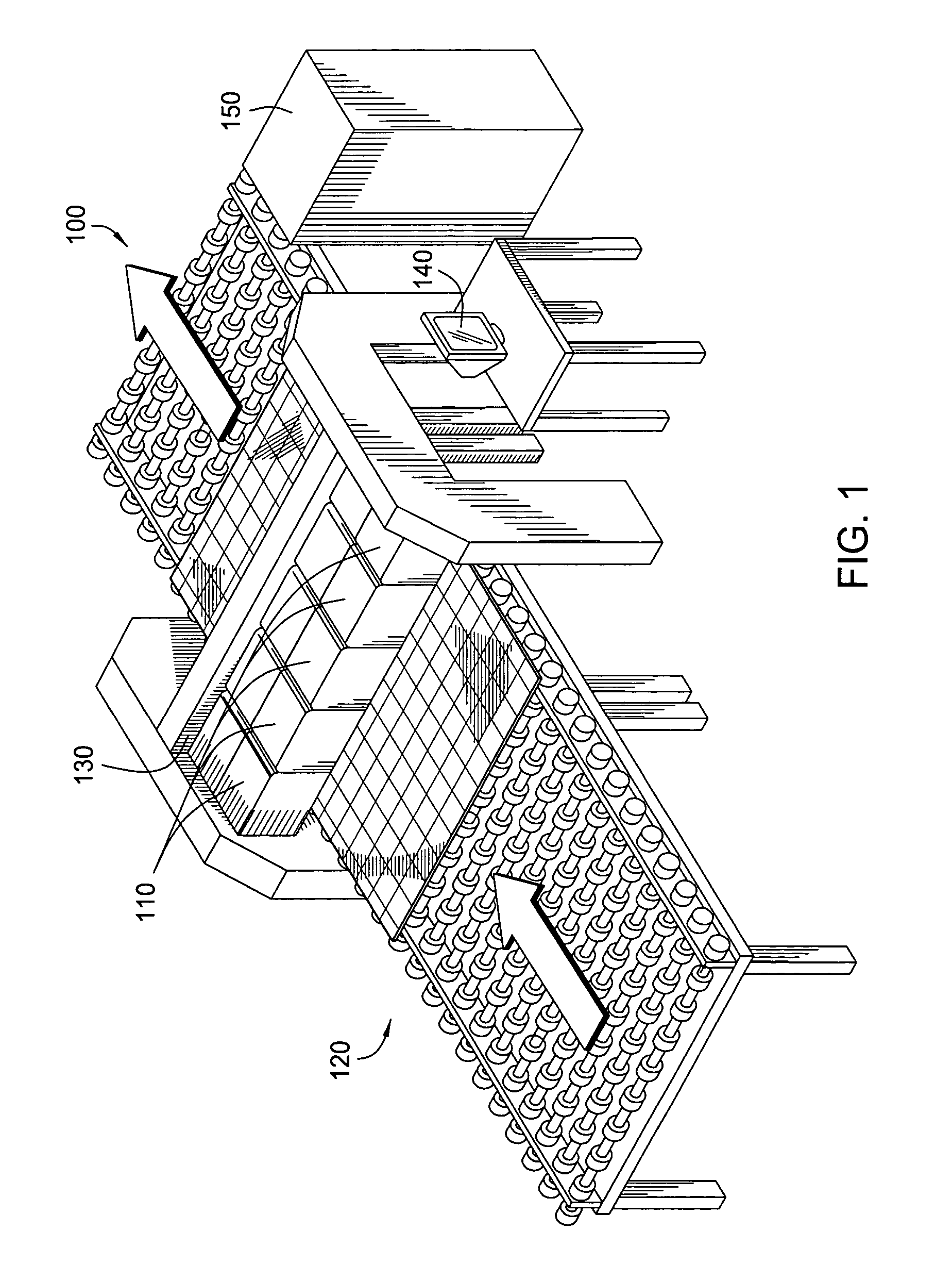
[0019] The present invention generally provides apparatus and techniques for automated optical inspection (AOI) utilizing image scanning modules with multiple objectives for each camera. A scanning mechanism includes optical components to sequentially steer optical signals from each of the multiple objectives to the corresponding camera. By freezing individual field of view images, motion accuracy requirements of the translation system used to move the inspected article may be greatly reduced when compared to scanning systems, such as “flying spot” laser scanning systems or systems based on constant illumination and linear imaging devices, for example, charge coupled devices (CCDs) or time delay and integrate (TDI) CCDs that require accurate motion control.

An Exemplary Inspection System

[0020]FIG. 1 illustrates an exemplary automated optical inspection (AOI) system 100 in accordance with embodiments of the present invention. The system 100 utilizes a plurality of image scanning mod...


PUM

PropertyMeasurementUnit
focal lengthaaaaaaaaaa
sizeaaaaaaaaaa

Abstract

Apparatus and techniques for automated optical inspection (AOI) utilizing image scanning modules with multiple objectives for each camera are provided. A scanning mechanism includes optical components to sequentially steer optical signals from each of the multiple objectives to the corresponding camera.

Description

BACKGROUND OF THE INVENTION [0001] 1. Field of the Invention [0002] Embodiments of the present invention generally relate to techniques for inspecting objects and, more particularly, to an automated optical inspection technique and system utilizing multiple objectives per camera. [0003] 2. Description of the Related Art [0004] Automated optical inspection (AOI) systems are used to inspect a wide variety of objects, such as semiconductor wafers and printed circuit boards (PCBs), for defects. Such systems typically utilize one or more image acquisition or “microscope” modules to capture images that cover the entire surface area of the object that is to be inspected. These images are then fed to some type of computer system for processing using various types of algorithms design to identify defects in the object. [0005] Typically, each image scanning module includes an illumination source to illuminate the portion of the article under inspection, some type of front lens assembly (refer...

Claims


Application Information

Patent Timeline
Patent Type & Authority Applications(United States)
IPC IPC(8): G01N21/00
CPCG01N21/8903
Inventor ALMOGY, GILADBOLT, BRYAN C.ARNON, ODEDKENAN, BOAZTIROSH, EHUDCORLISS, MICHAEL
Owner APPL MATERIALS ISRAEL LTD
Why Eureka
Try Eureka