Cooling system

a cooling system and cooling system technology, applied in the field of cooling systems, can solve the problems of system malfunction or slowdown, the size and weight of air-cooled solutions become more problematic, and traditional cooling approaches such as heat sinks and heat pipes cannot practically keep up with the growing heat problem, so as to minimize the amount of coolant spilled or leaked.

Inactive Publication Date: 2006-08-03
ONX COOLING SYST
View PDF14 Cites 21 Cited by
  • Summary
  • Abstract
  • Description
  • Claims
  • Application Information

AI Technical Summary

Benefits of technology

[0025] A quick connector for establishing coolant communications in a cooling system for cooling heat-generating components in an electronic system including; one more inserts; one or more receptacles for engaging with the inserts; and first sealing means within the inserts and receptacles for sealing the inserts and connectors when such inserts and receptacles are not engaged and for unsealing the inserts and receptacles when such inserts and receptacles are engaged, thereby enabling coolant communication there through.
[0026] The quick connecto

Problems solved by technology

As a result, more powerful cooling systems are required to prevent these components from thermal overload and resulting system malfunctions or slowdowns.
Traditional cooling approaches such as heat sinks and heat pipes are unable to practically keep up with this growing heat problem.
As these components become increasingly more powerful, the size and weight of air-cooled solutions become more problematic as well.
In smaller housings or rack mounted systems, the space required for air-cooled solutions becomes unacceptable.
For today's powerful microprocessors, for example, a bulky, heavy air cooled solution such as a heat sink or hea

Method used


Image

  • Cooling system
  • Cooling system
  • Cooling system

Examples


Embodiment Construction

[0042] Whilst the making and using of various embodiments of the present invention are discussed in detail below, it should be appreciated that the present invention provides many applicable inventive concepts, which can be embodied in a wide variety of specific contexts. The specific embodiments discussed herein are merely illustrative of specific ways to make and use the invention and do not limit the scope of the invention.

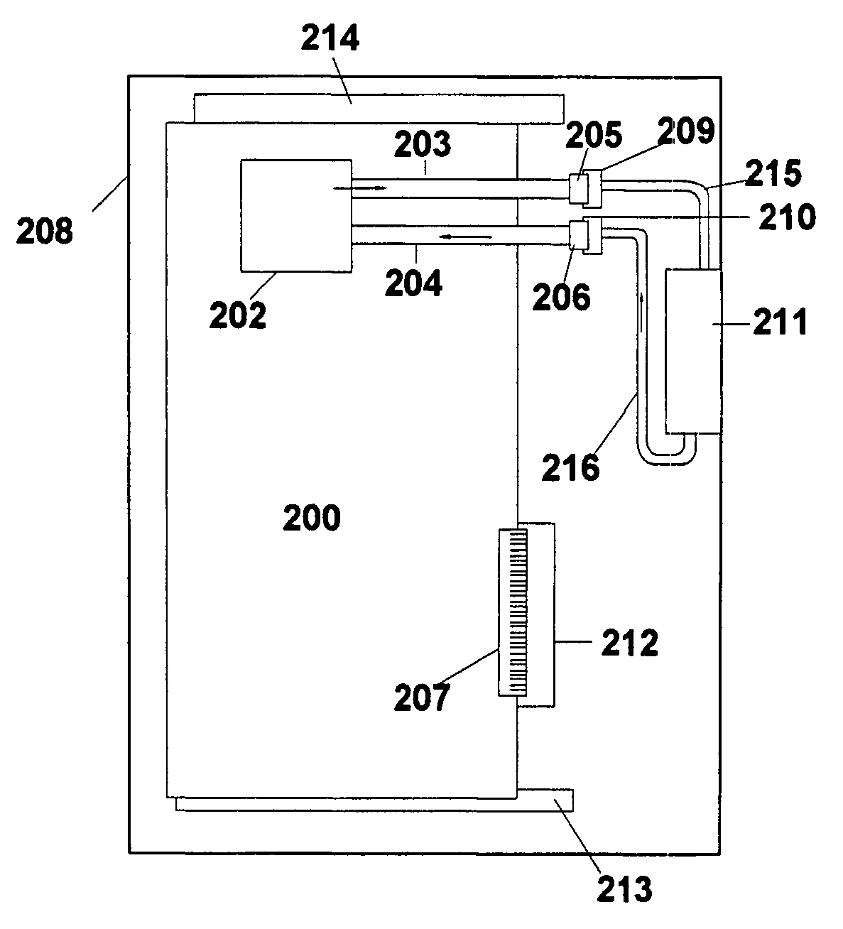
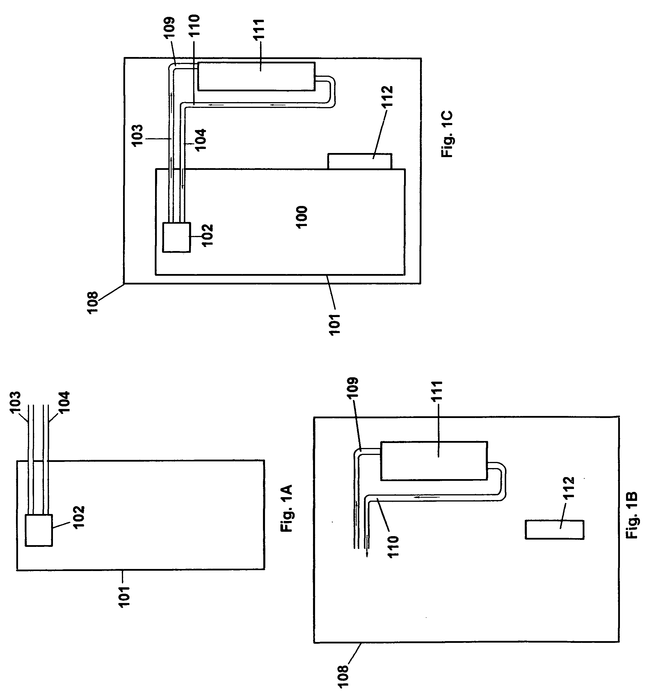
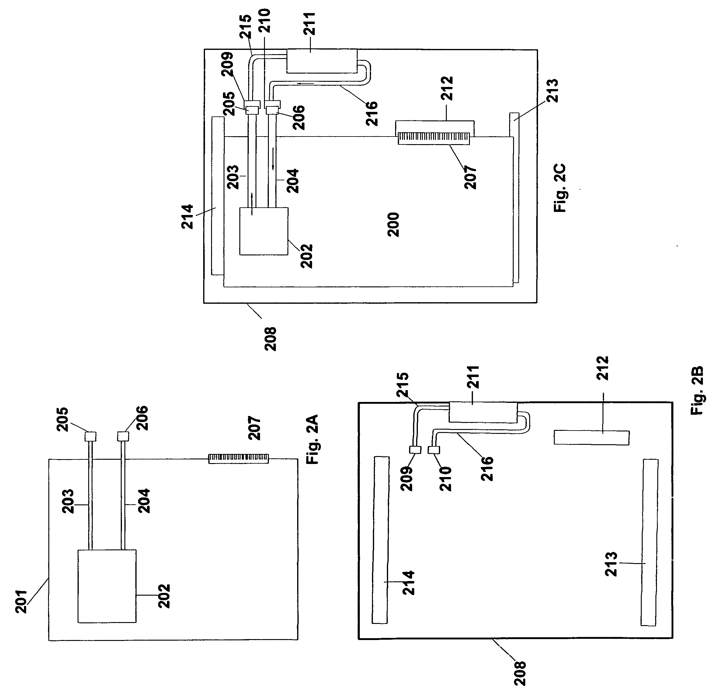
[0043] It should be understood that the principles and applications disclosed herein can be applied in a wide range of data processing systems, telecommunication systems and other systems such as electrical and electronic systems. In the present invention, heat produced by a heat generating component, such as, but not limited to, a microprocessor in a data processing system, is transferred to a coolant in a heat transfer unit and dissipated in the cooling system. Liquid cooling solves performance and reliability problems associated with heating of various heat...


PUM


Abstract

A cooling system with quick connectors is presented. A number of embodiments are presented. The cooling system includes one or more heat transfer units disposed on one or more circuit cards and thermally coupled to one or more heat generating components. As the circuit cards are inserted into or disconnected from an electronic system, coolant communication is enabled or disabled, respectively between one or more heat exchange units and the heat transfer units disposed on the circuit card at the time electrical connection of the circuit card is established or disconnected, respectively.

Description

CROSS REFERENCE TO RELATED APPLICATIONS [0001] This application is a continuation-in-part of pending U.S. patent application Ser. No. 10 / 964,344 filed Oct. 13, 2004. Reference is made to pending U.S. patent application Ser. No. 10 / 688,587 filed Oct. 18, 2003 for a detailed description of cooling systems and various heat transfer units and heat exchangers and their operation. Reference is also made to pending U.S. patent application Ser. No. 11 / 319,942 filed Dec. 29, 2005 for a detailed description of connector heat transfer units and to pending U.S. patent application Ser. No. 11 / 336,304 filed Jan. 23, 2006 for a detailed description of leakage or spillage sensors.BACKGROUND OF THE INVENTION Description of the Related Art [0002] At the heart of data processing and telecommunication devices are processors and other heat-generating components which are becoming increasingly more powerful and generating increasing amounts of heat. As a result, more powerful cooling systems are required...

Claims


Application Information

Patent Timeline
IPC IPC(8): H05K7/20
CPCF28D15/00F28D2021/0029F28D2021/0031G06F1/20G06F1/206H05K7/20781H05K7/20272
Inventor HAMMAN, BRIAN A.
Owner ONX COOLING SYST
Why Eureka
Try Eureka