
Orthopedic implant for mandibular advancer

a mandibular advancer and orthodontic technology, applied in the field of orthodontics, can solve the problems of unfavorable side effects, gum recession and root exposure, and reduce so as to facilitate the movement of the upper teeth backward and restrict the growth of the upper jaw

Inactive Publication Date: 2006-08-03
ORTHOARM
View PDF11 Cites 46 Cited by
  • Summary
  • Abstract
  • Description
  • Claims
  • Application Information

AI Technical Summary

Benefits of technology

[0010] The present invention provides a single or multi-piece orthopedic implant for anchoring mandibular advancer appliances. More particularly, the invention provides an orthopedic implant that is placed directly into the skeletal component of at least the lower jaw, thus creating an immutable and stable anchorage unit. Anchoring a Herbst appliance or spring advancer using the implant provided by the present invention applies a force to the skeletal component itself, rather than the dental component of the lower jaw, alleviating the above-described and other problems with existing Herbst appliances and spring advancers.
[0011] The orthopedic implant provided by the present invention may also be placed in the skeletal component of the upper jaw (maxilla). Orthopedic force to the implant when placed in the skeletal component of the upper jaw restricts natural forward growth of the upper jaw, assisting overjet correction.
[0012] In another construction, the maxillary anchorage may be placed directly on orthodontic elements, or directly on the dental component of the upper jaw, rather than in the skeletal component. This construction of the invention can facilitate moving the upper teeth backward, in addition to restricting forward growth of the upper jaw, further assisting overjet correction.

Problems solved by technology

This can lead to condylar (lower jaw joint bone) resorption.
By forcing the mandible forward with a compressed spring or fixed Herbst advancer, the lower dentition is pushed forward, sometimes off the base of the bone, resulting in unfavorable side-effects such as gum recession and root exposure.

Method used


Image

  • Orthopedic implant for mandibular advancer
  • Orthopedic implant for mandibular advancer
  • Orthopedic implant for mandibular advancer

Examples


Embodiment Construction

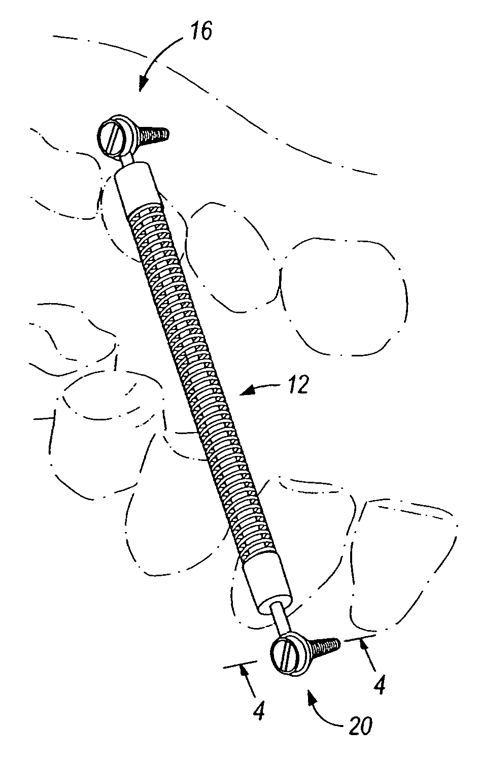
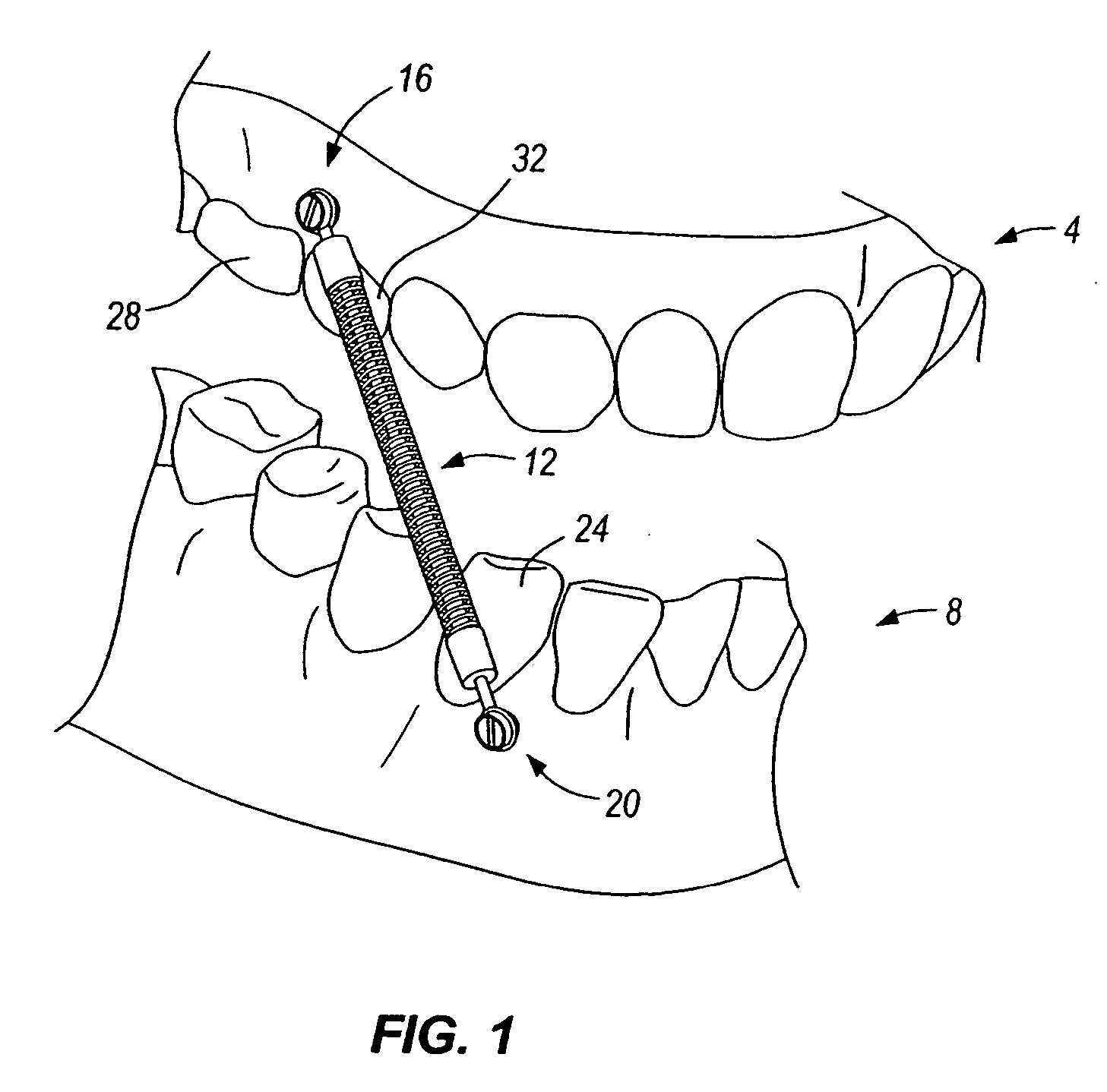
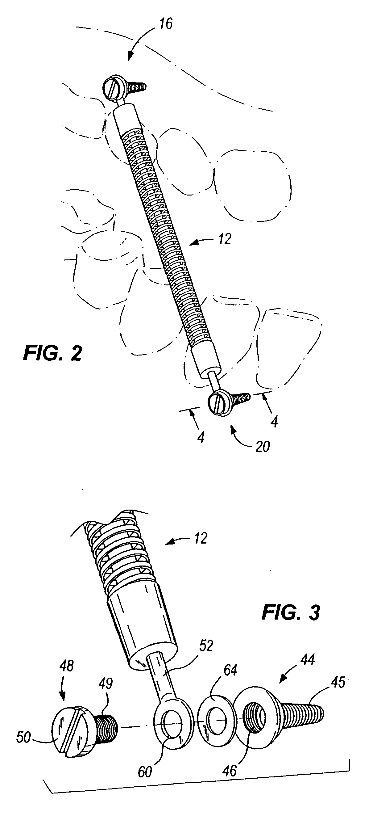
[0020]FIG. 1 illustrates an upper jaw 4, a lower jaw 8, and a mandibular advancer appliance 12 in an operating position. The mandibular advancer appliance 12 is anchored by upper and lower orthopedic implants 16, 20 embodying one construction of the invention. The lower implant 20 is shown embedded in the skeletal component of the lower jaw 8 in approximately the region of the mesial (forward) aspect of the mandibular canine 24. The upper implant 16 is shown embedded in the skeletal component of the upper jaw 4 between the maxillary first molar 28 and the maxillary second premolar 32.

[0021]FIG. 3 illustrates the lower implant 20 in greater detail. In the construction shown in FIG. 3, the multi-piece implant 20 includes a bone screw component 44, having both a male-threaded portion 45 and a female-threaded portion 46, and a securing screw component 48 including a male-threaded portion 49 and a head portion 50. The bone screw component 44 and securing screw component 48 may be constr...


PUM


Abstract

A mandibular advancer assembly comprising an advancer (e.g., a spring advancer, such as a Herbst appliance) having an upper end and a lower end, and a lower implant secured to the lower end of the advancer and adapted to be secured to the mandible of the patient. Preferably, the lower implant comprises a bone-engaging member (e.g., a bone screw) and a securing member for coupling the lower end of the advancer to the bone-engaging member. For example, the bone-engaging member can include a threaded orifice, and the securing member can include a threaded element engaged with the threaded orifice. If desired, the advancer assembly can further include an upper implant secured to the upper end of the advancer and adapted to be secured to the maxilla of the patient.

Description

FIELD OF THE INVENTION [0001] This invention relates to the field of orthodontics, and more particularly to mandibular advancers. BACKGROUND OF THE INVENTION [0002] The use of orthodontic mandibular advancer appliances to treat people with a small lower jaw (mandible) or receding chin is known. This horizontal projection of upper teeth beyond the lower teeth is also referred to as overjet. There are essentially two known types of lower jaw advancers: rigid Herbst advancers and spring advancers. [0003] Variations of the rigid Herbst advancer, often referred to as a Herbst appliance, include banded, stainless steel crown coverage, and cast-splint versions. All Herbst appliances rigidly hold the lower jaw forward and do not let it set back into the jaw joint socket (fossa). This can lead to condylar (lower jaw joint bone) resorption. [0004] There are several types of mandibular spring advancers, which are generally preferred over Herbst appliances due to the ability of the lower jaw to...

Claims


Application Information

Patent Timeline
IPC IPC(8): A61C3/00
CPCA61C7/36A61C8/0096
Inventor VOUDOURIS, JOHN C.
Owner ORTHOARM
Learn More