
Electrical plug connector

a plug connector and plug technology, applied in the direction of coupling device connection, coupling/disengagement of coupling parts, electric apparatus, etc., can solve the problems of no longer satisfying contact, no longer serving the purpose of the union nut, and no longer loosening of the screw means, so as to reduce production costs, increase process reliability, and simplify the effect of plug connector insertion and locking

Inactive Publication Date: 2006-08-03
CONINVERS ELEKTROTECHN BAUELEMENTE
View PDF1 Cites 13 Cited by
  • Summary
  • Abstract
  • Description
  • Claims
  • Application Information

AI Technical Summary

Benefits of technology

[0008] In one further advantageous refinement, the spring arms are additionally supported against the round housing in the region of the toothed profile by an additional spring element, preferably an O-ring. This measure means that greater force has to be applied in order to rotate the union nut and latching is made harder. The contact pressure in the circumferential locking toothed ring is therefore increased by means of the spring force of the O-ring and protection against unintentional loosening due to vibration is thus considerably improved.
[0009] In order to reliably fulfill is function, the O-ring is arranged precisely beneath the toothed profile and must not change its axial position, even when the union nut is turned or as a result of the union nut being turned. To this end, preferably at the corresponding location, the round housing has a circumferential groove in which the O-ring is mounted in a precise and stable position. This refinement also proves to be expedient when assembling the plug connector since the O-ring can be fitted in a simple and reliable manner.
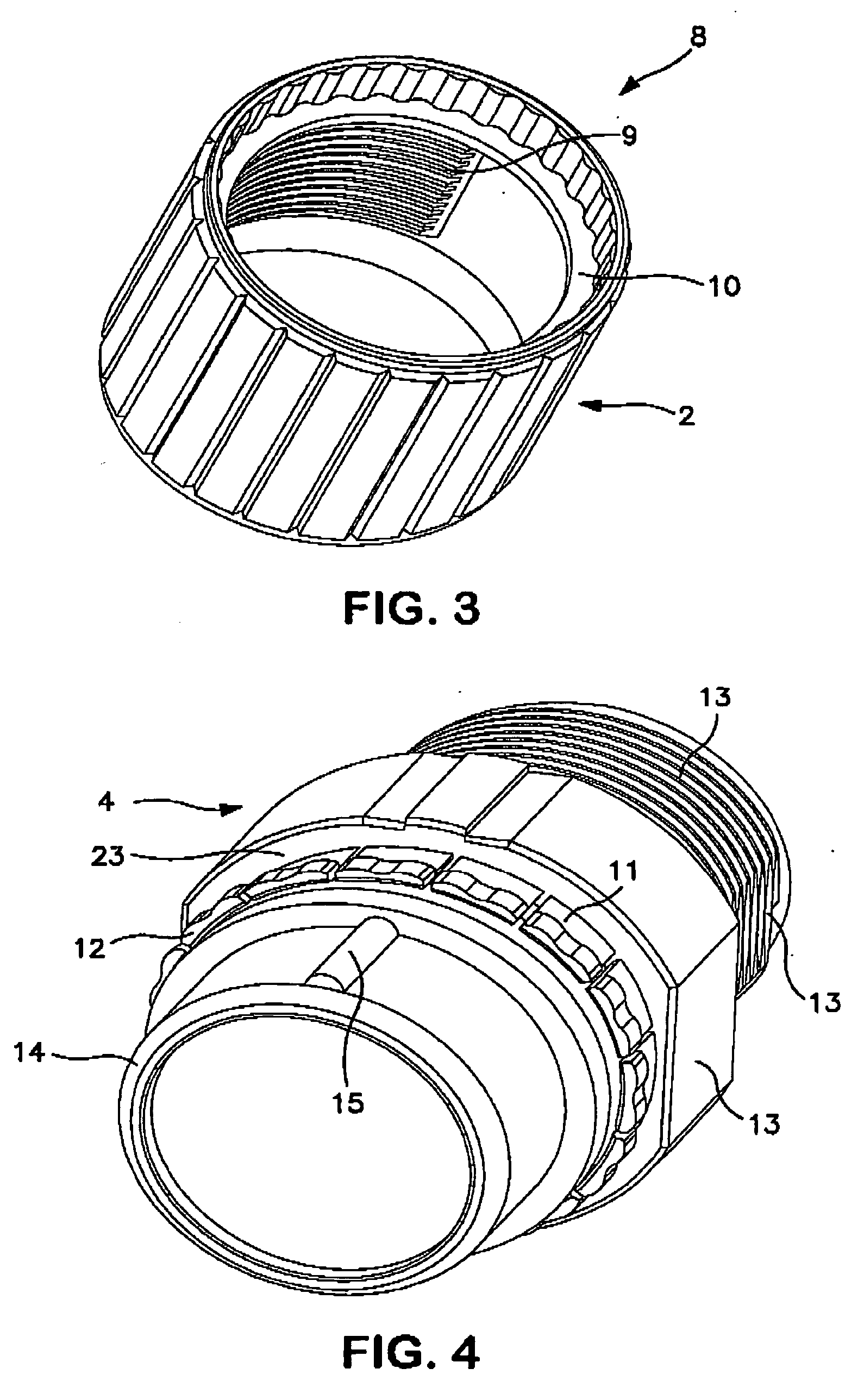
[0011] An internal thread, which has a plurality of turns and by means of which the plug connector is screwed to a mating connector part, is integrally formed in the union nut on the side associated with the mating connector part. In order to simplify insertion and locking of the plug connector, the internal thread is segmented. In this way, the union nut can be easily inserted into the mating connector part as far as the end position when the corresponding mating thread has a matching configuration, and can be firmly tightened by means of all of the turns of the thread by a slight turning movement. In this case, locking is possible even with a minimal axial engagement depth in the mating connector.
[0012] The union nut preferably has a locking toothed ring, which is open toward the corresponding end face, on the inner circumference of the side facing the fixing ring. This preferred refinement means it is possible to reduce production costs for the injection-molding dies and increase their process reliability.
[0014] The fixing ring and union nut advantageously have additional latching elements by means of which the union nut can be placed in preferred positions in relation to the plug housing. To this end, one or more additional toothed profiles are expediently integrally formed, offset in the axial direction, on the spring arms which protrude from the fixing ring and engage in a second locking toothed ring of the union nut. A marker provided on the fixing ring points toward the polarity-reversal protection means which is integrally formed on the round housing and is concealed by the union nut. This aid considerably simplifies insertion of the plug connector for the user. In one further advantageous embodiment, the latching position is supplemented on one side by a fixed stop and the function of a bayonet fitting is thus achieved in conjunction with the segmented internal thread of the union nut.

Problems solved by technology

However, if the plug connection is subject to a large number of, in particular, periodic shocks and / or a shaking movement, there is a high risk of the screwing means coming loose, so that the purpose of the union nut is no longer served and satisfactory contact is no longer ensured.

Method used


Image

  • Electrical plug connector
  • Electrical plug connector
  • Electrical plug connector

Examples


Embodiment Construction

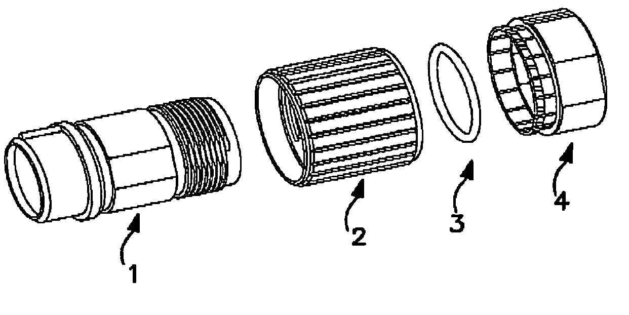
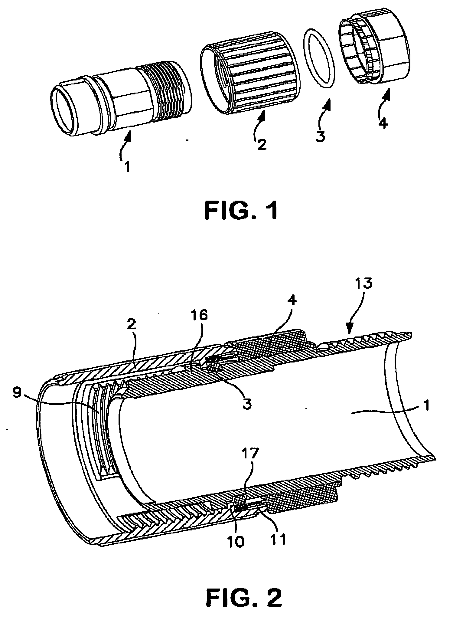
[0025]FIG. 1 shows the design of the electrical plug connector which comprises a round housing 1, a union nut 2, an O-ring 3 and a fixing ring 4. During the assembly process, first the union nut 2 and then the O-ring 3 are screwed onto the round housing 1 and secured by the fixing ring 4.

[0026]FIG. 2 shows a longitudinal section through the middle plane of an assembled plug connector. The union nut 2 is screwed onto the round housing 1 in such a way that its internal thread 9 points in the direction of the plug front, that is to say toward the mating connector part, and a radial collar 10 which is situated on the inner circumference of said union nut rests on a stop collar 16 on the round housing 1. This prevents the union nut 2 from falling out in the direction of the mating connector part. When the union nut 2 is screwed onto a mating connector part, the collar 10 acts as a driver and presses the circumferential stop collar 16 of the round housing 1 against the mating connector p...


PUM


Abstract

An electrical plug connector comprises a simple and inexpensive rotation-securing element for the union nut of a water-tight plug connection which ensures reliable connection in the event of shocks and vibration, and in the process produces different values for the tightening torque and loosening torque of the screwed connection. The plug connector has a threaded union nut which is screwed to its plug housing and is secured against unintentional rotation with respect to the housing by two mutually engaging locking toothed rings having an asymmetric, sinusoidal toothed profile. The locking toothed ring which is attached to a fixing ring for the union nut is segmented, is elastically sprung and contains additional latching elements for preferred positions of the union nut.

Description

BACKGROUND OF THE INVENTION [0001] The invention relates to an electrical plug connector, in which the body of at least one male connector part has a union nut which can be screwed to an associated mating connector part, said union nut being secured against unintentional rotation with respect to the body by latching means, with one of the latching means in each case being integrally formed on the body, and the corresponding other latching means being arranged on the union nut, and one of the latching means being in the form of a circumferential locking toothed ring. [0002] In order to secure the plug connection of two plug connectors which are connected to one another, it is known to mount a union nut on one of the two connector parts such that it can rotate, said union nut being screwed to a thread provided on the connector mating piece, after which the plug connection is made. Such prevention of rotation makes assembly work easier when installing electrical systems in which a larg...

Claims


Application Information

Patent Timeline
IPC IPC(8): H01R4/38
CPCH01R13/5202H01R13/622
Inventor SCHOLLER, JOHANNFREDL, SONJA
Owner CONINVERS ELEKTROTECHN BAUELEMENTE
Learn More