Systems and methods for photo-mechanical hearing transduction

a technology of photo-mechanical and sound transduction, applied in the direction of optical signal transducers, implantable hearing aids, and completely in canal hearing aids, etc., can solve the problem of mechanical or electrical failure of the connection between the light transmission component and the output transducer assembly

Active Publication Date: 2006-08-24
EARLENS CORP
View PDF99 Cites 173 Cited by
  • Summary
  • Abstract
  • Description
  • Claims
  • Application Information

AI Technical Summary

Benefits of technology

[0017] The input transducer assembly will often be configured to be worn behind the pinna of the subject's ear in a manner similar to a conventional hearing aid. Alternatively, the transducer assembly could be configured to be worn within the ear canal, in the temple pieces of eyeglasses, or elsewhere on the subject such as in the branches of eyeglasses. In most cases, the input transducer assembly will further comprise a light transmission component which delivers light from the light source to the output transducer assembly. Typically, the light transmission component will be adapted to pass through the subject's auditory canal (ear canal) to a position adjacent to the output transducer assembly. In the most common embodiments, the output transducer assembly will reside on the tympanic membrane, and the light transmission component will have a distal terminal end which terminates near the output transducer assembly. Thus, the light transmission component will preferably not be mechanically connected to the output transducer assembly, and there will typically be a gap from 2 mm to 20 mm, preferably from 4 mm to 12 mm, between the distal termination end of the light transmission component and the output transducer assembly. This gap is advantageous since it allows the output transducer assembly to float freely on the tympanic membrane without stress from the light transmission component, and with minimum risk of inadvertent contact with the light transmission component. Additionally, there is no connection between the light transmission component and the output transducer assembly which is subject to mechanical or electrical failure.
[0018] Light, unlike an electromagnetic field produce by a coil, does not suffer from large changes in intensity resulting from small variations in distance or angle. Simply put, the laws of physics that govern the propagation of light describe the fact the light intensity will not substantially change over the distances considered in this application. Furthermore, if the “cone of light” produced between the end of the transmission element and the light-sensitive opto-mechanical transducer has an appropriate angle, small changes in the relative angle between the light transmission element and the output transducer will have no substantial change in the light energy received by the light sensitive area of the output transducer. Because the transmission of power and information using light is far less sensitive to distance and angle than when using electromagnetic field, the energy coupling between the input and output transducers of this invention is far less dependent on the exact position between them. This reduces the need for very tight tolerances designing the overall system, and hence eliminating the requirement for a custom manufactured input transducer mold. As compared to the prior art, the present invention can reduce the manufacturing costs, improve the comfort, simplify the insertion and removal of the input transducer, and allow for less potential changes in the energy coupling between the input and the output transducers.
[0021] In still further embodiments, the input transducer assembly may comprise a light source which is located immediately adjacent to the output transducer assembly, thus eliminating the need for a separate light transmission component. Usually, in those cases, the light transducer component will be connected to the remaining portions of the input transducer assembly using electrical wires or other electrical transmission components.
[0024] In a preferred embodiment where the support component is adapted to contact the tympanic membrane, the surface of the support component will have an area sufficient for manually releasably supporting the output transducer assembly on the membrane. Usually, the support component will comprise a housing at least partially enclosing the transducer component, typically fully encapsulating the transducer component. A surface wetting agent may be provided on the surface of the support component which contacts the tympanic membrane. Alternatively, the polymer used to fabricate the output transducer may provide sufficient coupling forces with the tympanic membrane without the need to periodically apply such a wetting agent.

Problems solved by technology

Additionally, there is no connection between the light transmission component and the output transducer assembly which is subject to mechanical or electrical failure.

Method used


Image

  • Systems and methods for photo-mechanical hearing transduction
  • Systems and methods for photo-mechanical hearing transduction
  • Systems and methods for photo-mechanical hearing transduction

Examples


Embodiment Construction

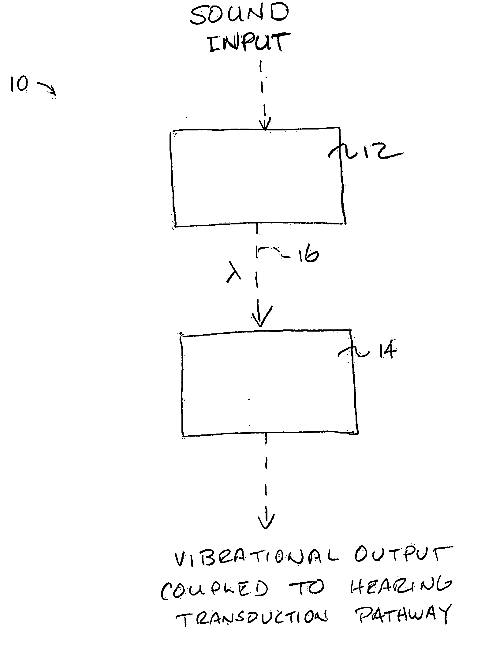
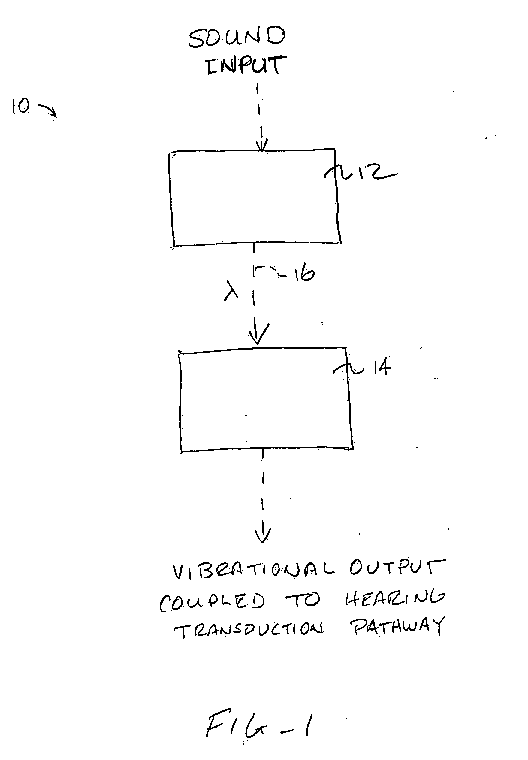
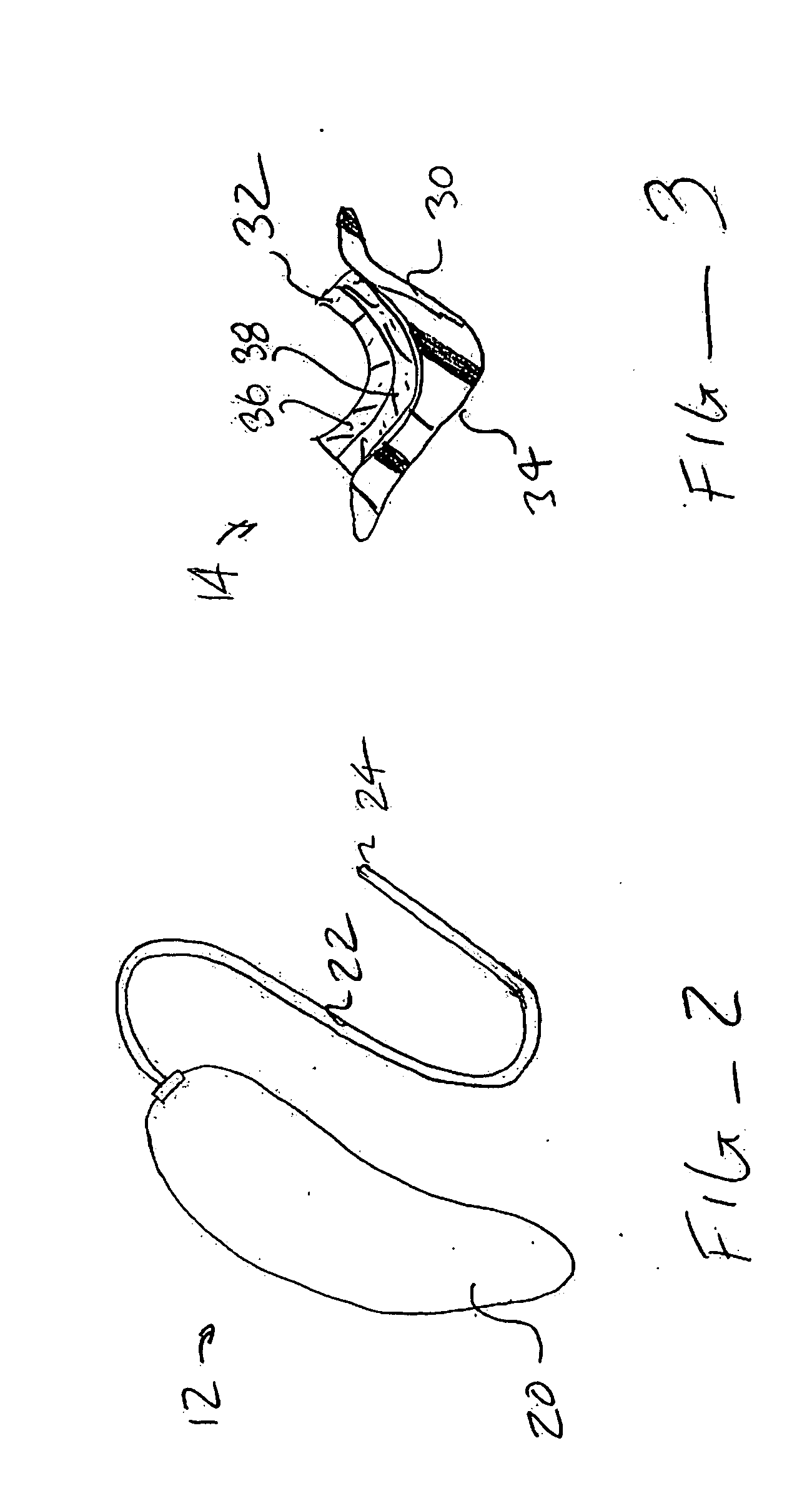
[0050] As shown schematically in FIG. 1, systems 10 constructed in accordance with the principles of the present invention will comprise an input transducer assembly 12 and an output transducer assembly 14. The input transducer assembly 12 will receive a sound input, typically either ambient sound (in the case of hearing aids for hearing impaired individuals) or an electronic sound signal from a sound producing or receiving device, such as the telephone, a cellular telephone, a radio, a digital audio unit, or any one of a wide variety of other telecommunication and / or entertainment devices. The input transducer assembly will produce a light output 16 which is modulated in some way, typically in intensity, to represent or encode a “light” sound signal which represents the sound input. The exact nature of the light input will be selected to couple to the output transducer assembly to provide both the power and the signal so that the output transducer assembly can produce mechanical vi...


PUM


Abstract

Hearing systems for both hearing impaired and normal hearing subjects comprise an input transducer and a separate output transducer. The input transducer will include a light source for generating a light signal in response to either ambient sound or an external electronic sound signal. The output transducer will comprise a light-responsive transducer component which is adapted to receive light from the input transducer. The output transducer component will vibrate in response to the light input and produce vibrations in a component of a subject's hearing transduction pathway, such as the tympanic membrane, a bone in the ossicular chain, or directly on the cochlea, in order to produce neural signals representative of the original sound.

Description

CROSS-REFERENCES TO RELATED APPLICATIONS [0001] The present application is a non-provisional of U.S. Patent Application Ser. No. 60 / 618,408 (Attorney Docket No. 022237-000800US), filed Oct. 12, 2004, the full disclosure of which is incorporated herein by reference.BACKGROUND OF THE INVENTION [0002] 1. Field of the Invention [0003] The present invention relates generally to systems and methods for sound transduction. In particular, the present invention relates to the use of light signals for producing vibrational energy in a transduction pathway from a subject's tympanic membrane to the subject's cochlea. [0004] A wide variety of hearing aids and ear pieces have been produced over the years to provide sound directly into a subject's ear. Most such hearing systems rely on acoustic transducers that produce amplified sound waves which impart vibrations directly to the tympanic membrane or ear drum of the subject. Hearing aids generally have a microphone component which converts ambient...

Claims


Application Information

Patent Timeline
Patent Type & Authority Applications(United States)
IPC IPC(8): H04R25/00
CPCH04R23/008H04R25/554H04R25/606H04R2225/023H04R2225/67
Inventor PLUVINAGE, VINCENT
Owner EARLENS CORP
Why Eureka
Try Eureka