Radio controlled helicopter

a technology of radio control and helicopter, applied in the field of helicopters, can solve the problems of disadvantages, mechanical complexity, and difficulty in coordinating directional flight controls, and achieve the effect of preventing damage to the first rotor and safe operation of the inventive helicopter

Inactive Publication Date: 2007-09-20
SHANTZ MICHAEL +1
View PDF34 Cites 58 Cited by
  • Summary
  • Abstract
  • Description
  • Claims
  • Application Information

AI Technical Summary

Benefits of technology

[0007] An advantage of the present invention is the elimination of one set of helicopter flight controls, so that even an inexperienced pilot can satisfactorily fly the inventive helicopter with minimal risk of collision.
[0008] A further advantage of the present invention is in the ability to operate the inventive helicopter safely indoors.
[0009] Additional advantages and other features of the present invention will be set forth in part in the description which follows and in part will become apparent to those having ordinary skill in the art upon examination of the following or may be learned from the practice of the invention. The advantages of the invention may be realized and obtained as particularly pointed out in the appended claims.
[0010] According to the present invention, the foregoing and other advantages are achieved in part by a helicopter comprising a body, a first rotor, a propulsion unit substantially rigidly attached to the body and having a first shaft for mounting and rotatably driving the first rotor, and a mass adjustably mounted to the body for changing a center of gravity of the helicopter.
[0011] In another aspect of the present invention, the helicopter comprises a rotor protector to protect persons from injury from the first rotor and to prevent damage to the first rotor due to contact with objects during flight. The rotor protector comprises a support tube rotatably mounted over the first shaft; a safety ring having a diameter greater than that of the first rotor and supported by the support tube such that it is substantially level with the first rotor; and a tether for flexibly attaching the rotor protector to a tail of the helicopter for preventing the rotor protector from spinning.
[0012] A still further aspect of the present invention is a helicopter comprising a body; a first rotor; a second rotor; a propulsion unit substantially rigidly attached to the body, the propulsion unit having a propulsion motor, a first drive shaft attached to the motor for mounting and rotatably driving the first rotor, and a second drive shaft coaxial to the first shaft and attached to the motor, for mounting and rotatably driving the second rotor in an opposite direction to the first rotor at substantially the same speed as the first rotor; a substantially vertically aligned tail rotor for controlling yaw of the helicopter during flight, the tail rotor having a plane of rotation intersecting a center of mass of the helicopter and being disposed a predetermined distance from the center of mass of the helicopter; a reversible motor for rotating the tail rotor; and a mass rigidly mounted to the body such that a center of gravity of the helicopter is forward of the first and second drive shafts.

Problems solved by technology

Radio controlled helicopters present operating difficulties related to coordination of directional flight controls, due to a multiplicity of such controls.
In an attempt to effectively control the flight path, the pilot of a radio controlled helicopter can easily become confused, or can cross control the aircraft, resulting in a collision.
Although this design improves the stability of the helicopter, it is mechanically complex, usually requiring two motors (one for each rotor).
Such complexity is disadvantageous because it adds cost and weight to the helicopter.
Another disadvantage of conventional radio controlled helicopters is that they are not practical to use indoors, such as in a relatively small living space, because their rotor(s) are easily damaged during a collision with a wall or ceiling.
Moreover, persons in the room can be injured by the rotor(s).

Method used


Image

  • Radio controlled helicopter
  • Radio controlled helicopter
  • Radio controlled helicopter

Examples


Embodiment Construction

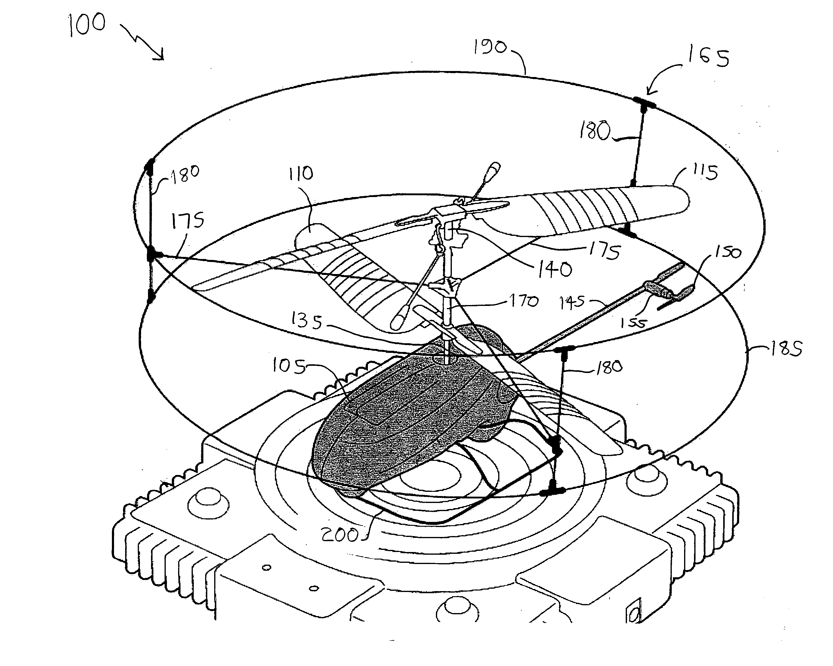
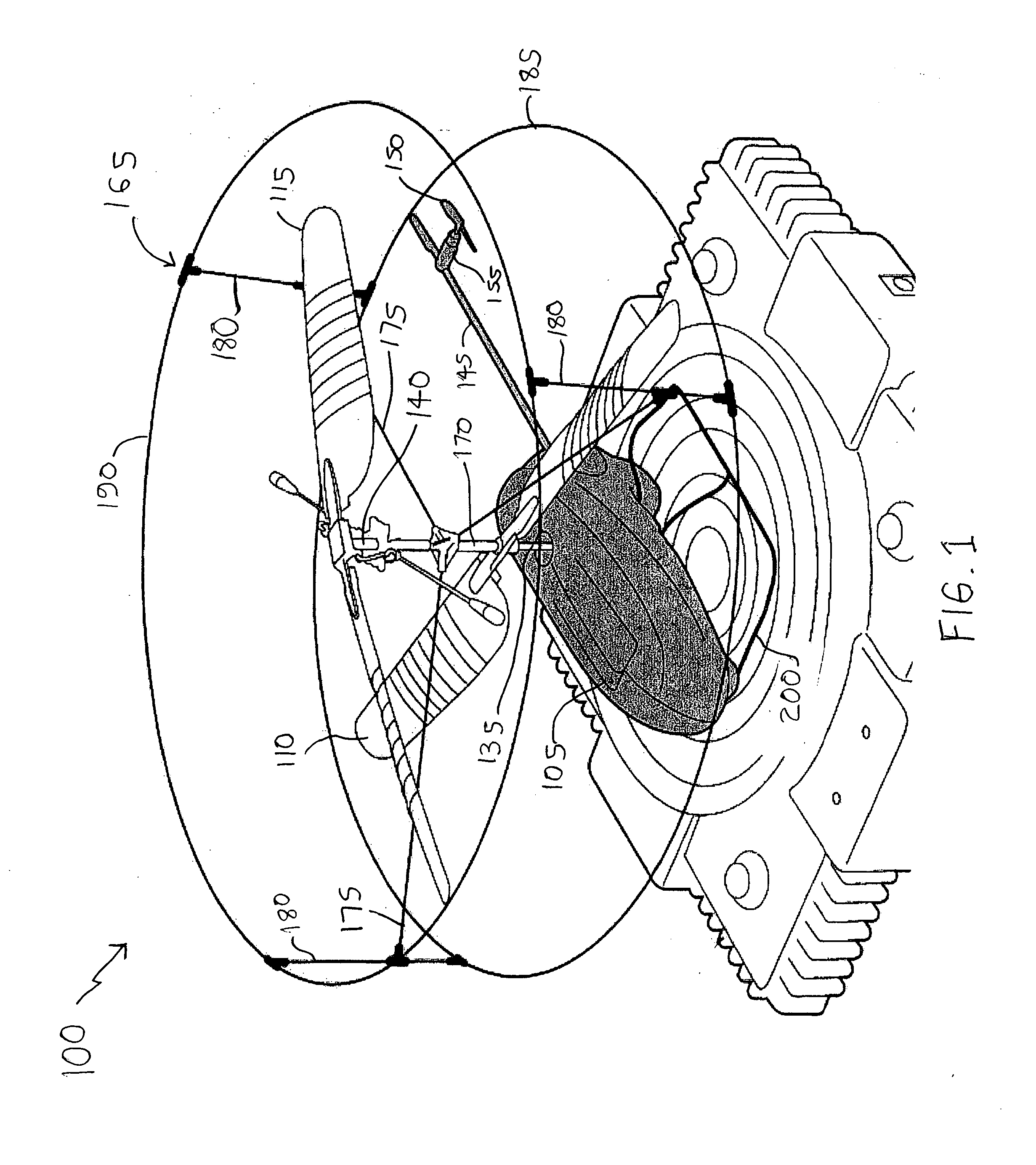
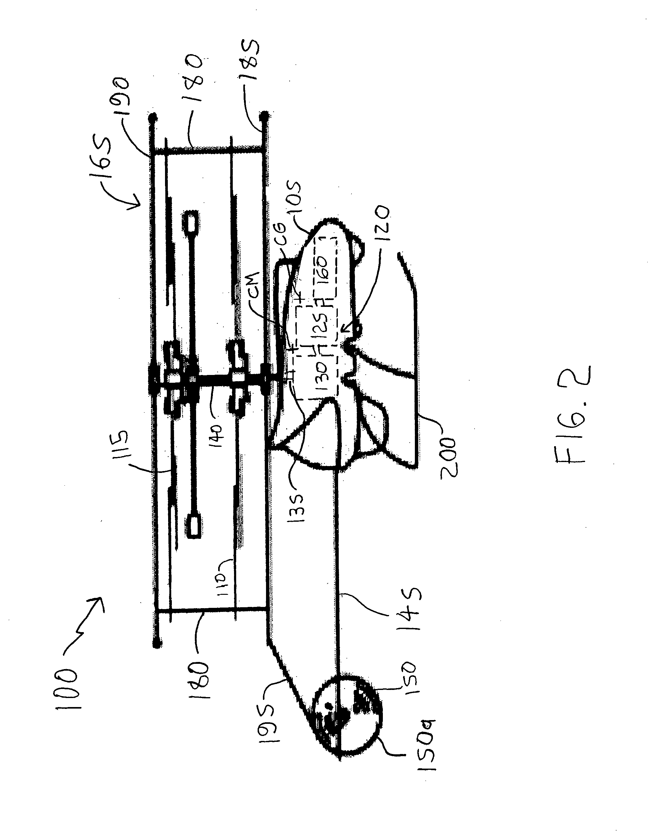
[0018] The present invention provides an easily operated radio controlled helicopter, by eliminating or simplifying the sideslip flight control. In an embodiment of the present invention; a forward directional flight path is achieved by placing the center of gravity of the helicopter forward of the center of lift (i.e., the center of the rotor(s)) by locating the power supply battery in a forward area of the helicopter fuselage. The result is a helicopter which is always moving forward and inherently stable. The pilot need only be concerned with power, which controls altitude and descent, and with left / right steering, which is effected through a conventional tail rotor that controls yaw.

[0019] In certain embodiments of the present invention, a helicopter comprises two counter rotating rotors which are driven by a single motor at a fixed 1:1 relative rotation speed. The forward speed of the inventive helicopter can be adjusted by manual movement of the battery relative to the forwar...


PUM


Abstract

A radio controlled helicopter is provided which eliminates or simplifies forward / reverse flight control for safe and easy indoor operation. Embodiments include a helicopter having a pair of counter rotating rotors which are driven at the same speed, a vertically aligned tail rotor driven by a reversible motor for controlling yaw, and a mass, such as a power supply battery, mounted for changing the center of gravity of the helicopter to adjust the tendency of the helicopter to move in a forward or reverse direction. The mass is either rigidly mounted, so that the helicopter is always moving forward during flight, or adjustably mounted so that the helicopter's forward or reverse direction can be adjusted prior to or during flight. A protective cage is provided to protect persons from injury from the rotors and to prevent damage to the rotors due to contact with objects during flight.

Description

CROSS REFERENCE TO RELATED APPLICATION [0001] This application claims priority under 35 U.S.C. §119 from Provisional Patent Application No. 60 / 737,807, filed on Nov. 18, 2005. The entire subject matter of the application is incorporated herein by reference.FIELD OF THE INVENTION [0002] The present invention relates to helicopters. The present invention has particular applicability in radio controlled helicopters which can be flown indoors. BACKGROUND ART [0003] Radio controlled helicopters present operating difficulties related to coordination of directional flight controls, due to a multiplicity of such controls. Typically, the pilot must simultaneously operate four controls: altitude (ascent / descent), heading (forward / reverse), rotation (left / right) and side to side movement or “sideslip” (left / right). In an attempt to effectively control the flight path, the pilot of a radio controlled helicopter can easily become confused, or can cross control the aircraft, resulting in a collis...

Claims


Application Information

Patent Timeline
Patent Type & Authority Applications(United States)
IPC IPC(8): B64C27/08
CPCA63H30/04A63H27/12
Inventor SHANTZ, MICHAELKEENNON, MATTHEW
Owner SHANTZ MICHAEL
Why Eureka
Try Eureka