Automatic braking and locking of a wind turbine

a technology of automatic braking and wind turbines, which is applied in the direction of wind energy generation, motors, engine fuctions, etc., can solve the problems of increasing the risk of service personnel being injured, the locking device may be damaged, and the manual actuation and especially the manual positioning of the locking disk will be increasingly difficult for service personnel to achieve the effect of reducing the risk associated and increasing work safety

Inactive Publication Date: 2007-08-16
S B PATENT HLDG
View PDF7 Cites 58 Cited by
  • Summary
  • Abstract
  • Description
  • Claims
  • Application Information

AI Technical Summary

Benefits of technology

[0007] In view of the problems in the state of the art, one embodiment of the invention shows a wind energy installation that addresses the task of making possible a cost-effective process for the operation of a wind energy installation and lowers the risk associated with maintenance procedures. In one embodiment, difficulties associated with the operation and the maintenance of a wind energy insta

Problems solved by technology

In light of the ever increasing installation size and associated rotor diameters, wind energy installations may use stronger and often heavier locking devices.
Manual actuation and especially manual positioning of the locking disk will be increasingly more difficult for the service personnel, especially when the rotor should a

Method used


Image

  • Automatic braking and locking of a wind turbine
  • Automatic braking and locking of a wind turbine

Examples


Embodiment Construction

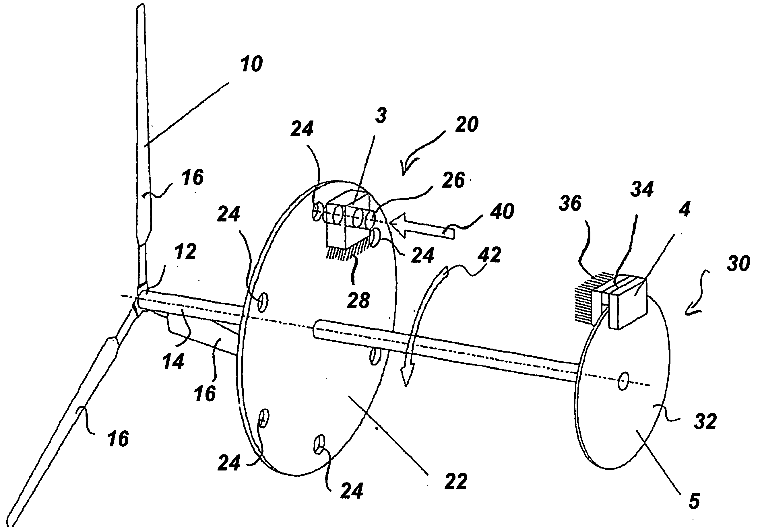
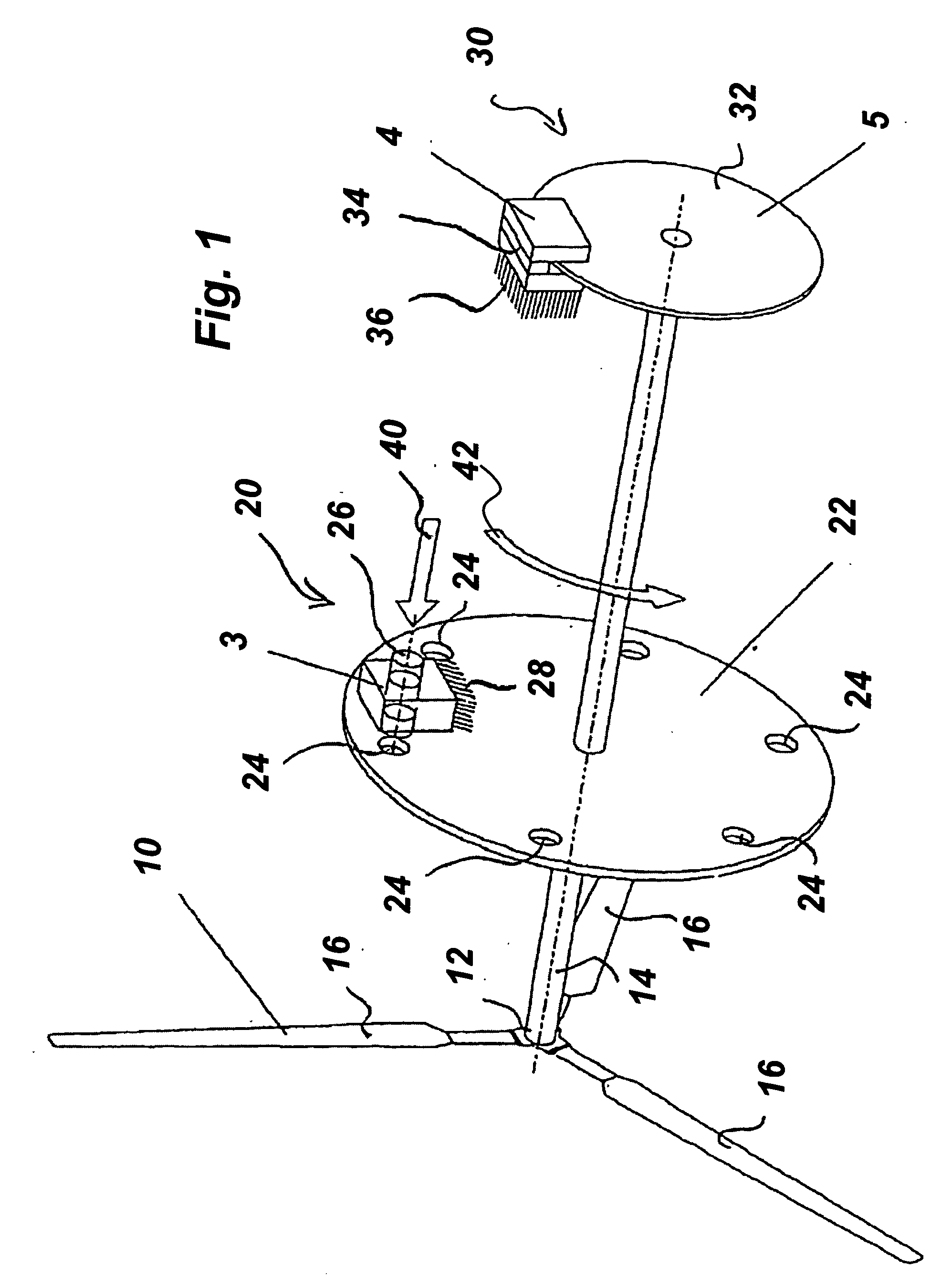
[0019] In the following detailed description, reference is made to the accompanying drawing which forms a part hereof wherein like numerals designate like parts throughout, and in which are shown, by way of illustration, a specific embodiment in which the invention may be practiced. It is to be understood that other embodiments may be utilized and structural or logical changes may be made without departing from the scope of the present invention. Therefore, the following detailed description is not to be taken in a limiting sense, and the scope of the present invention is defined by the appended claims and equivalents thereof.

[0020] Reference in the specification to “one embodiment” or “an embodiment” means that a particular feature, structure, or characteristic described in connection with the embodiment is included in at least one embodiment. The appearances of the phrase “in one embodiment” in various places in the specification do not necessarily all refer to the same embodimen...


PUM


Abstract

A wind turbine rotor is decelerated and locked in a target rotational position in relation to rotation of the rotor about the rotor axis. The rotational position of the rotor in relation to the rotational axis is detected relative to at least one target rotational position. Once the rotor reaches one of the target rotational positions, the rotor is halted and automatically locked in the target rotational position.

Description

CROSS REFERENCE TO RELATED APPLICATIONS [0001] The present application claims priority to co-pending German Application No. 10 2004 013 624.6, filed Mar. 19, 2004, the International Priority of which is claimed under 35 U.S.C. § 119, and International Application No. PCT / EP2005 / 002712, filed Mar. 14, 2005, the Priority of which is claimed under 35 U.S.C. § 120; the entire contents and disclosures of which are hereby incorporated by reference in their entirety.TECHNICAL FIELD [0002] The one embodiment of the invention pertains to a process for the operation of a wind energy installation by which a rotor of the wind energy installation is decelerated and locked in a desired rotational position with respect to rotation about the rotational axis, as well as a wind energy installation capable of executing such a process. BACKGROUND [0003] In general, wind energy installations include a tower with a nacelle mounted on the tower that can be rotated on an approximately vertical rotational a...

Claims


Application Information

Patent Timeline
IPC IPC(8): F03D9/00H02P9/04F03D1/00F03D7/02
CPCF03D1/003F03D7/0244Y02E10/723F05B2260/90F03D7/0268F03D80/50Y02E10/72F05B2260/31
Inventor STRUVE, JANFRANKE, MICHAEL
Owner S B PATENT HLDG
Why Eureka
Try Eureka