Osteosynthesis device

a technology of osteosynthesis and device, applied in the field of osteosynthesis devices, can solve the problems of difficult measurement of hka value, damage to bone integrity, damage to bone, etc., and achieve the effect of any risk of wrenching or playing

Inactive Publication Date: 2012-01-19
OSTESYS
View PDF2 Cites 23 Cited by
  • Summary
  • Abstract
  • Description
  • Claims
  • Application Information

AI Technical Summary

Benefits of technology

[0021]First of all, since the first attachment means can be easily made out of a material that is harder than bone, for example metal or ceramic, small-sized coupling surfaces are enough to ensure the desired mechanical coupling on the bracket, without any risk of wrenching or of play. The coupling elements according to an embodiment of the invention can thus be miniaturized. On the contrary, in the prior art, bone requires relatively long screws of a fairly big diameter to distribute the stresses and thus prevent any swivel which would be a source of lack of precision of the identified position and would damage the bone.
[0075]An information system can thus help in the desired navigation.

Problems solved by technology

During the operation, it is difficult to measure the value of the HKA because the above joint centers are purely geometrical, i.e. they are not visible elements.
One drawback of such a process is that the position trackers and their attachment screws take up space and are therefore inconvenient during the osteotomy.
Furthermore, these screws harm the integrity of the bone, and do so specifically in an area that will additionally receive the attachment screws of the osteosynthesis plate.
On the contrary, in the prior art, bone requires relatively long screws of a fairly big diameter to distribute the stresses and thus prevent any swivel which would be a source of lack of precision of the identified position and would damage the bone.
Thus, the patient's discomfort is limited.

Method used


Image

  • Osteosynthesis device
  • Osteosynthesis device
  • Osteosynthesis device

Examples


first embodiment

1. First Embodiment

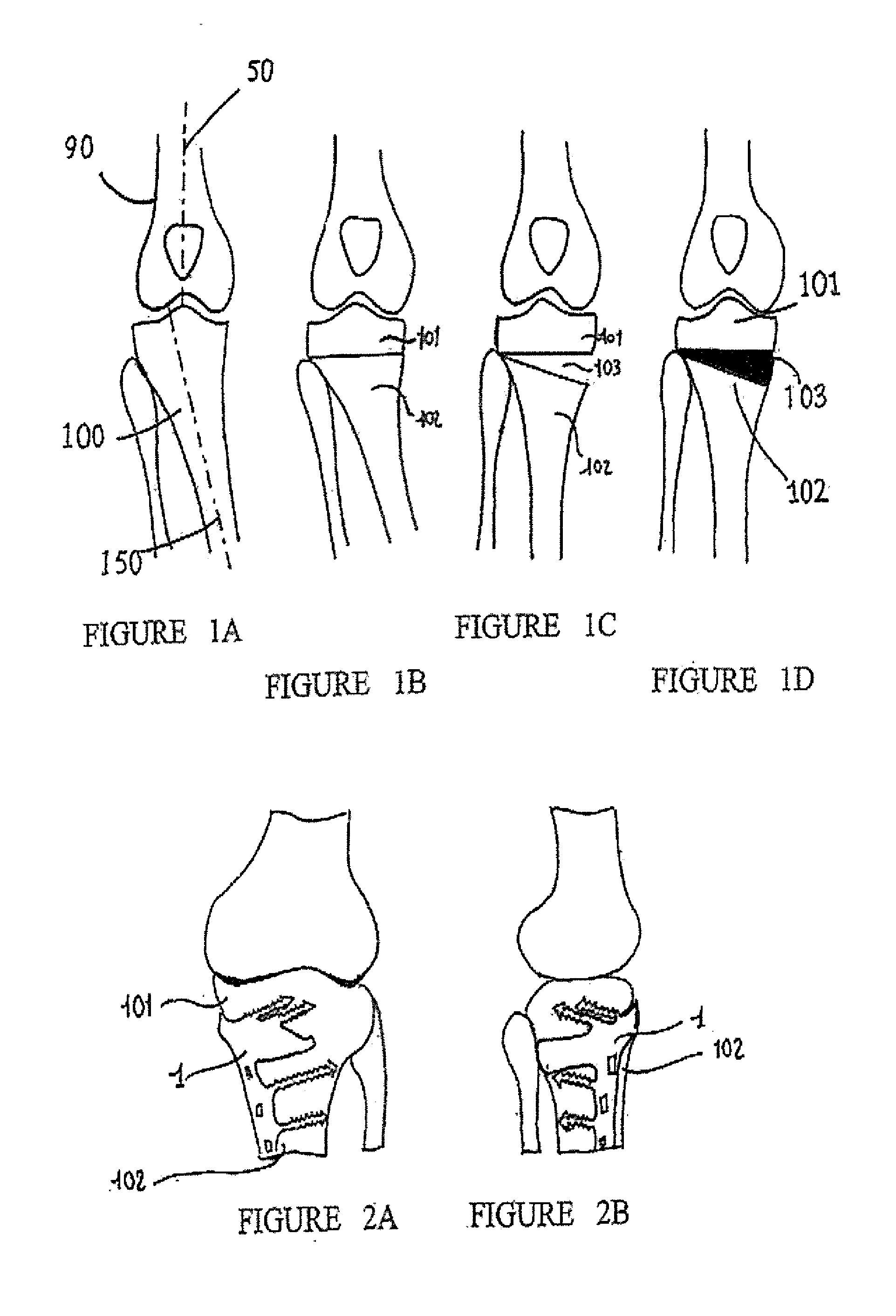
[0109]FIGS. 1A to 1D schematically illustrate the progress of an osteotomy operation for opening a bone 100 which in this case is a tibia, i.e. an elongated bone. Clearly, the bone 100 could be any other bone whose shape has to be modified by incision.

[0110]In FIG. 1A, a femur 90 has a direction of extension 50 which represents precisely a straight line linking a geometrical center of rotation of the upper end of the femur 90, situated in the hip, to a geometrical center of rotation at the knee. The tibia 100 has a direction of extension 150 which corresponds to a straight line linking its geometrical center of rotation of the knee with its geometrical center of rotation at the ankle It can be seen that the directions 50, 150 have a relative obliqueness which is excessive. It is therefore necessary to make the tibia 100 pivot in a clockwise direction in order to reduce this angle.

[0111]FIG. 1B shows that an osteotomy is made on the tibia 100, i.e. that the tibia i...

second embodiment

2. Second Embodiment

[0155]FIG. 15 is a view in perspective of the second embodiment of an osteosynthesis plate. The elements identical to those of the first embodiment have kept their reference numbers and the functionally homologous elements carry an additional suffix B.

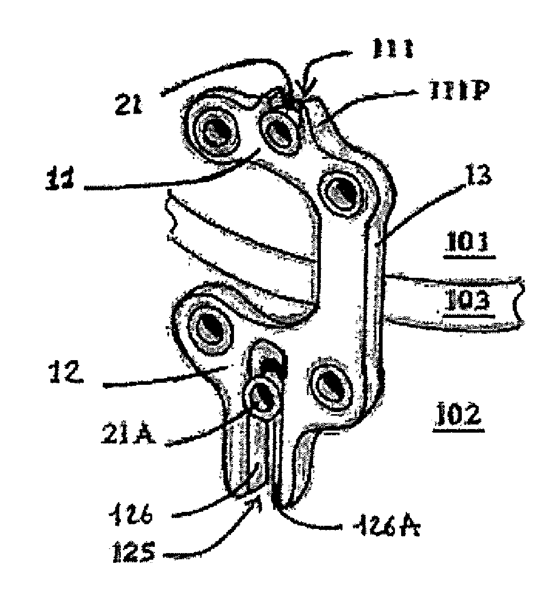
[0156]The plate 1B of the second embodiment has an overall shape similar to that of the plate 1, with a first base 11B, a second base 12B and a linking tab 13B. However, it differs from the plate 1 in the fact that the first attachment hole 111B in the first base 11B is a hole with a closed rim, that is circular or axially oblong. The aperture 125, herein referenced 125B, is in duplicate, and forms an axially oblong hole with a closed rim. It will be noted however that the fact the rim of the first attachment hole 111B and the apertures 125 are closed does not constitute a necessary characteristic, but means only that the coupling with the attachment and support screws 21B, 21AB does not require a cut in this rim.

[0...

third embodiment

3. Third Embodiment

[0165]FIG. 21 is a plane view illustrating a third embodiment. The elements homologous to an element of the first embodiment bear the same numerical reference followed by the suffix C.

[0166]One original feature of the third embodiment lies in the fact that the monoblock unit formed by the three functional elements 11-13 is replaced by an assembly of three separate elements, namely a first base 11C and a second base 12C which serve as bases for an adjustable element for their mutual linkage, in the form of a strap 13C, which herein is a strap in duplicate to improve the stability and enable the setting of the slope and of the aperture.

[0167]The first base 11C is functionally identical to the first base 11 and similarly has three holes 111C, 112C, 113C, each for a classic screw or a first attachment and support screw 21. As in the case of the first base 11, the holes 111C and 113C are not aligned and, specifically, are arranged according to the vertices of a substan...


PUM


Abstract

An osteosynthesis device is provided. The device includes a first screw for attaching a first holding base to a first section of a bone, a second screw for attaching a second holding base to a second section of the bone, and a rigid linking element mutually connecting the first and second bases. Either the first screw or the first base has a cavity for receiving a bracket of an associated position-marking device.

Description

CROSS-REFERENCE TO RELATED APPLICATIONS[0001]This Application is a Section 371 National Stage Application of International Application No. PCT / EP2010 / 051035, filed Jan. 28, 2010 and published as WO 2010 / 086390 A1 on Aug. 5, 2010, not in English.STATEMENT REGARDING FEDERALLY SPONSORED RESEARCH OR DEVELOPMENT[0002]None.THE NAMES OF PARTIES TO A JOINT RESEARCH AGREEMENT[0003]None.FIELD OF THE DISCLOSURE[0004]The disclosure pertains to osteosynthesis devices.[0005]When a person has a bone structure with deformed legs, such that the knees are excessively or insufficiently apart in the standing position, then the weight of the body, which is unequally distributed at the knee, can cause arthrosis. To remedy this problem, the above-mentioned deformation needs to be eliminated as far as possible by the by changing the direction of extension (re-tilting or axial correction) of the tibia to bring it into a predetermined angular range relatively to the femur. The optimal range is considered to ...

Claims


Application Information

Patent Timeline
Patent Type & Authority Applications(United States)
IPC IPC(8): A61B17/56
CPCA61B17/8019A61B2019/5483A61B17/809A61B17/8023A61B2090/3983
Inventor STINDEL, ERICLEFEVRE, CHRISTIAN
Owner OSTESYS
Why Eureka
Try Eureka