Valve gasket for a metering valve

a valve gasket and valve gasket technology, which is applied in the direction of engine seals, packaging, engine components, etc., can solve the problems of valve rod sticking, valve gasket leakage, valve rod leakage total,

Inactive Publication Date: 2003-09-23
APTAR FRANCE SAS
View PDF12 Cites 25 Cited by
  • Summary
  • Abstract
  • Description
  • Claims
  • Application Information

AI Technical Summary

Benefits of technology

An object of the invention is to provide a valve gasket for a metering valve that is designed to avoid undesired sticking of the valve rod due to friction between it and the valve gasket, while said valve rod is moving relative to the valve gasket, while also guaranteeing leaktightness at said valve gasket during this movement.
Another object of the invention is to provide a valve gasket that is designed to enable the valve rod to operate reliably and safely with a spring of low stiffness, thereby making it easier to actuate.
Yet another object of the invention is to provide a metering valve that operates with a propellant gas that is not harmful to the environment, said valve including a valve rod that can slide in the valve gasket between its actuating position and its rest position under the effect of the spring without leakage and without any risk of it sticking.
To these ends, the invention provides a valve gasket for a metering valve serving to dispense a fluid in the form of a powder dispersed in a propellant gas, said metering valve comprising a valve body defining a metering chamber, and a valve rod mounted to slide in said metering chamber between a rest position and an actuating position, the sealing between said valve rod and said metering chamber being provided by said valve gasket, said valve body being fixed in a fixing cap serving to assemble the valve onto a fluid reservoir, said valve gasket being provided with a radially inside contact zone over which said valve rod slides, said contact zone being fixed to a rigid element so that, while said valve rod is moving, said contact zone of the valve gasket remains substantially unchanging in terms of its shape and of its position, said contact zone having a profile that is rounded at least in part, so as to reduce the area of contact between said valve gasket and said valve rod, said rigid element being an integral part of said fixing cap, and in particular the inside radial edge thereof. Thus, for given dimensions of the valve rod, said rod slides with lower friction, thereby avoiding sticking of the valve rod, while also guaranteeing excellent leaktightness.
The use of such a valve gasket thus makes it possible to avoid any deformation of the valve gasket, thereby preventing any fluid from being trapped between the rod and the gasket.

Problems solved by technology

A problem that arises with the valve rods of valves, in particular of metering valves, concerns in particular leaktightness at the valve gasket.
Secondly, when the valve rod is in the rest position, the leaktightness must be total in spite of the pressure inside the metering chamber and inside the receptacle.
A drawback with such a configuration lies in the fact that the friction that appears while the valve rod is sliding can be relatively high, which can result in said valve rod sticking.
In particular, when the fluid is in the form of a powder, this can hinder or even prevent metering valve operation.
Unfortunately, the use of such "environmentally-friendly" gases implies a major increase in the pressure inside the valve body, it being possible for such an increase to be as large as 50%.
It is therefore necessary to provide even greater leaktightness at the valve gasket, which implies even higher friction between the valve rod and said gasket.
However, that requires a considerable amount of force to be exerted in order to actuate the metering valve, which is undesirable.
That solution is relatively satisfactory with propellant gases such as CFCs, but it is not satisfactory when HFA gases are used.
HFA gases expel the silicone during use of the valve, so that after it has been used a certain number of times, the problem of the valve rod sticking reappears.

Method used


Image

  • Valve gasket for a metering valve
  • Valve gasket for a metering valve
  • Valve gasket for a metering valve

Examples


Embodiment Construction

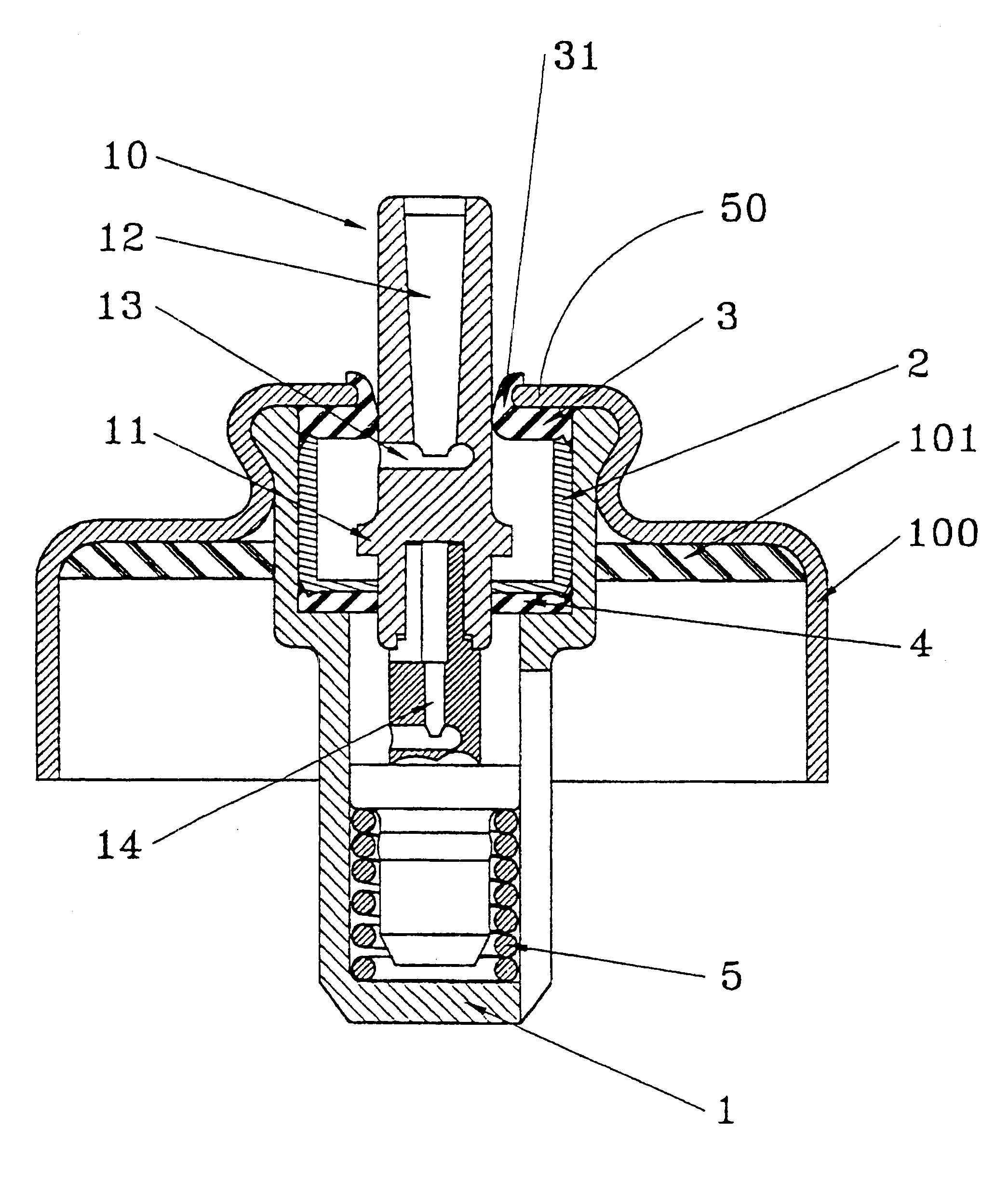
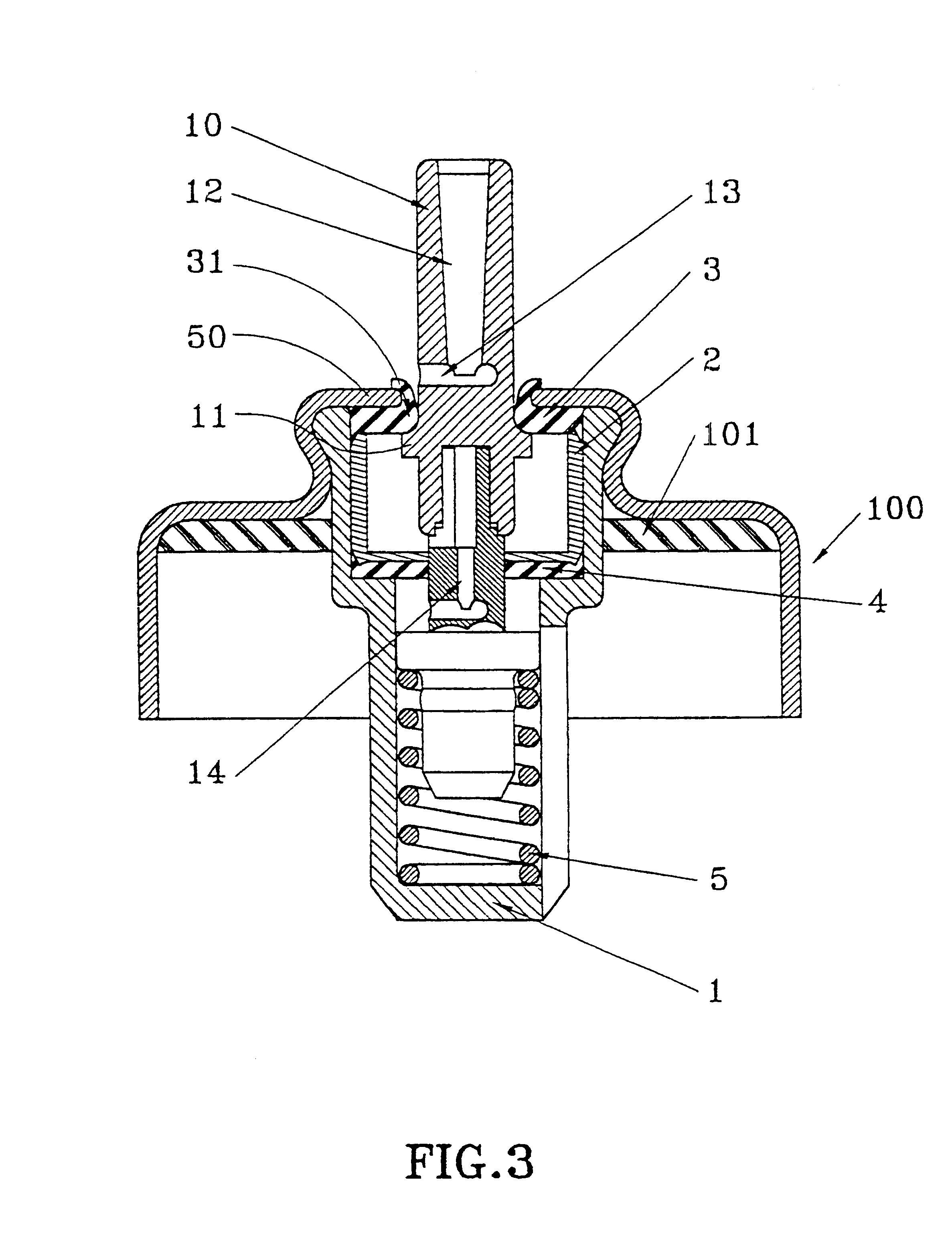
The invention is described below with reference to an example of a metering valve as shown in the drawings, but clearly it is applicable to metering valves of all types.

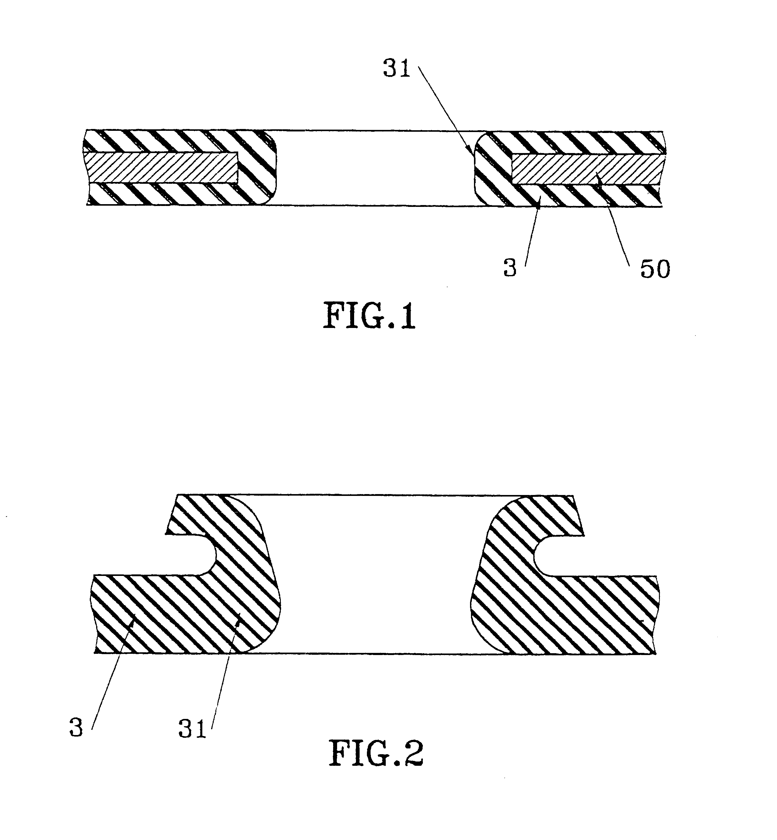
With reference to FIGS. 3 and 4, a metering valve may include a valve body 1 enclosing a metering chamber 2. The metering chamber 2 may be defined axially by two annular gaskets, namely a valve gasket 3 and a chamber gasket 4. Each of the two gaskets may be provided with a central opening through which a valve rod 10 passes. The valve rod is mounted to move inside the valve body 1 between a rest position shown in FIG. 3 and an actuating position shown in FIG. 4. The valve rod 10 may be urged into its rest position by a resilient member such as a spring 5 that abuts at one end against the bottom of the valve body 1, and at its other end against the bottom end of the valve rod.

The valve body 1 may be fixed, e.g. crimped, in a cap 100 which is then fixed, e.g. by crimping, to the neck of a receptacle or flask of any typ...


PUM


Abstract

A valve gasket for a metering valve serving to dispense a fluid, in particular a powder dispersed in a propellant gas, the metering valve including a valve body defining a metering chamber, and a valve rod mounted to slide in the metering chamber between a rest position and an actuating position, the sealing between the valve rod and the metering chamber being provided by the valve gasket, the valve body being fixed in a fixing cap serving to assemble the valve onto a fluid reservoir, the valve gasket being provided with a radially inside contact zone over which the valve rod slides, the contact zone being fixed to a rigid element so that, while the valve rod is moving, the contact zone of the valve gasket remains substantially unchanging in terms of its shape and of its position, the contact zone having a profile that is rounded at least in part, so as to reduce the area of contact between the valve gasket and the valve rod, the rigid element being an integral part of the fixing cap, and in particular the inside radial edge thereof.

Description

The present invention relates to an improved valve gasket for a metering valve, and to a fluid dispenser device including a metering valve provided with such an improved valve gasket.Dispenser device valves are well known in the state of the art. They are mainly used with aerosol receptacles for dispensing fluids charged with propellant (dissolved gas under pressure). When the valve is a metering valve, it generally comprises a valve body enclosing a metering chamber defined axially by two annular gaskets, namely a valve gasket and a chamber gasket, and a valve rod mounted to move between a rest position and an actuating position. The valve rod is urged by a spring into its rest position, in which a shoulder on said rod bears against the bottom surface of said valve gasket. In order to actuate the metering valve, it is necessary to press on the valve rod which slides in the valve body inside the annular gaskets until it reaches its actuating position, in which a metered quantity of ...

Claims


Application Information

Patent Timeline
Patent Type & Authority Patents(United States)
IPC IPC(8): B65D83/14B05B9/04B65D83/44F16J15/16
CPCB65D83/54
Inventor LEONE, PATRICEBARRANCO, SANDRINEDI GIOVANNI, PATRICK
Owner APTAR FRANCE SAS
Why Eureka
Try Eureka