Online Anti-feedback system for a hearing aid

a hearing aid and anti-feedback technology, applied in the field of hearing aid anti-feedback system, can solve the problems of howling and instability of hearing aids, and achieve the effects of reducing the risk, reducing the max gain, and increasing the risk of howling

Inactive Publication Date: 2010-09-16
OTICON
View PDF7 Cites 31 Cited by
  • Summary
  • Abstract
  • Description
  • Claims
  • Application Information

AI Technical Summary

Benefits of technology

[0060]In a particular embodiment, the effect of the OFBM is limited, e.g. to + / −5 dB of the initial max gain. In a particular embodiment, the OFBM is constrained to a predefined maximum change, e.g. only to be allowed to make maximum of + / −2 dBs of change. This has the advantage of reducing the risk of making too large and sudden changes (e.g. increases in gain). In a particular embodiment, the OFBM is constrained to only be able to decrease the max gain.
[0061]In a particular embodiment, the effect of the OFBM is adapted to be frequency dependent in that the adjustment of maximum (and / or minimum) gain in at least one frequency band is different from other frequency bands.
[0062]In a particular embodiment, the OFBM is adjustable in the fitting situations in that e.g. a choice between higher gain / higher risk of howls or lower gain / lower risk of howls can be made. By increasing the (‘predefined’) maximum allowable loop gain (LGmax,i(pd)), the signal is better in certain situations, but the risk of experiencing howl in certain situations is increased, and vice versa.
[0063]In a particular embodiment, the OFBM is adapted to use information from other sub systems (e.g. environmental detectors or external signals indicating the kind or acoustical environment currently present) in the HA to increase the performance by making the decisions more confident (e.g. by influencing the update frequency).

Problems solved by technology

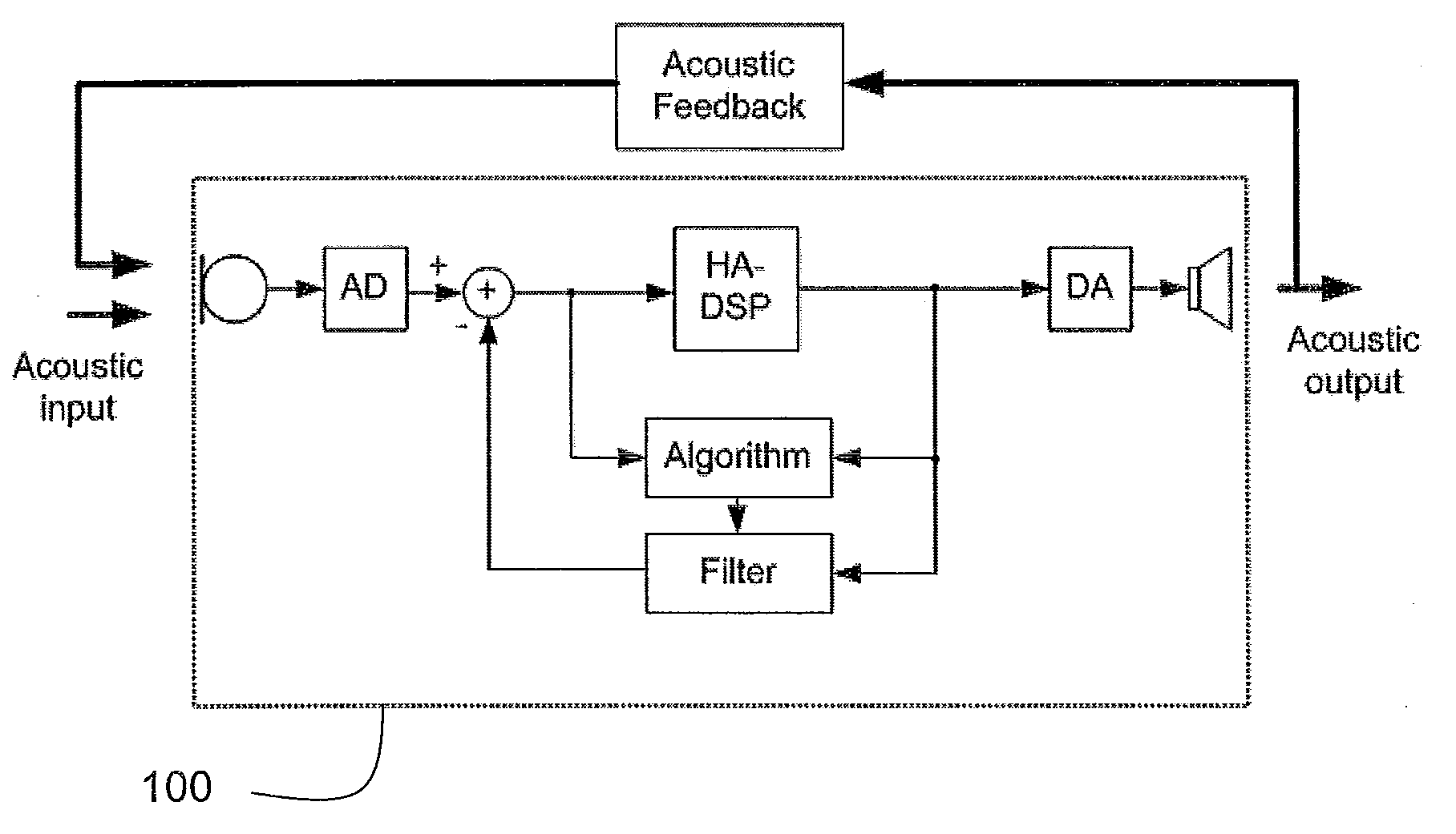
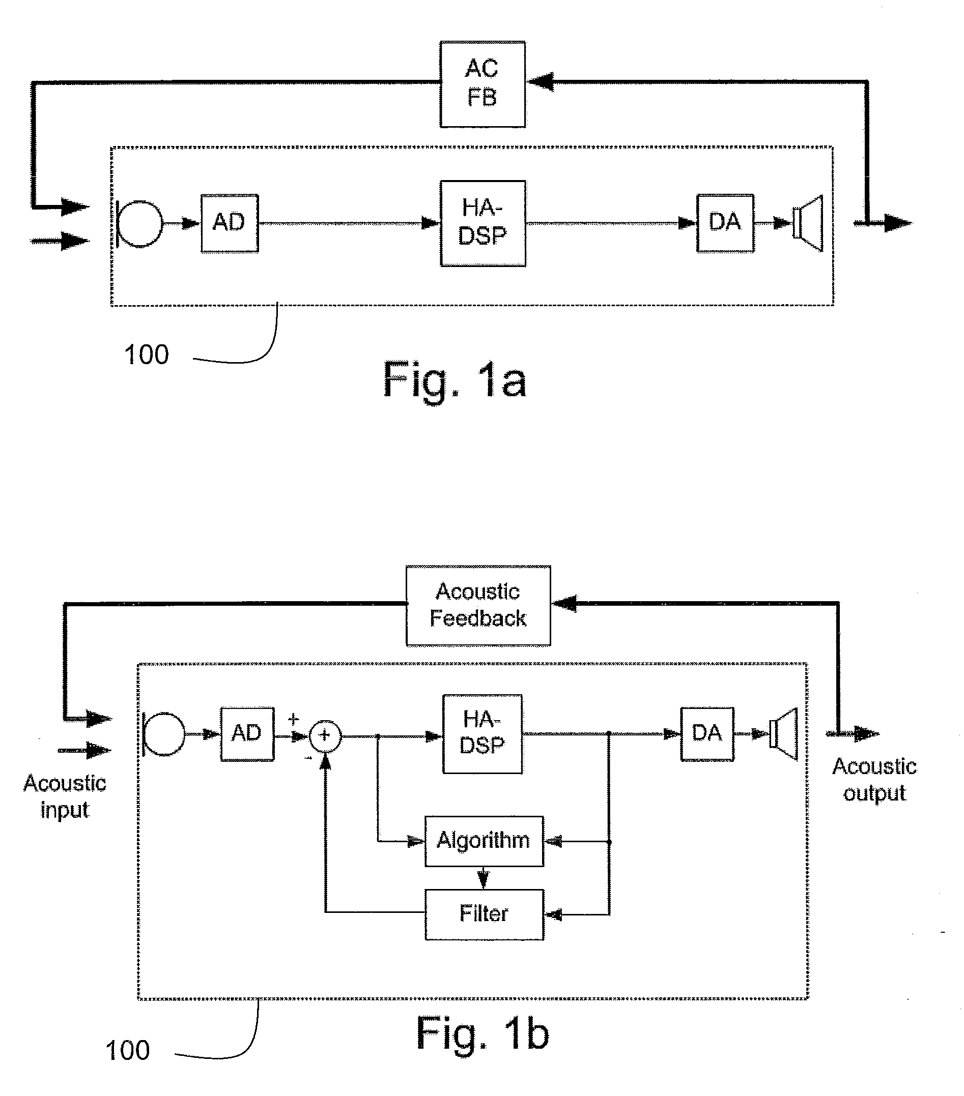
It is a well known problem that a hearing aid can become unstable and howl when loop gain exceeds 1.

Method used


Image

  • Online Anti-feedback system for a hearing aid
  • Online Anti-feedback system for a hearing aid
  • Online Anti-feedback system for a hearing aid

Examples


example 1

OFBM1, Use of an (Relatively Fast) OFBM as an AFB-System

Standalone:

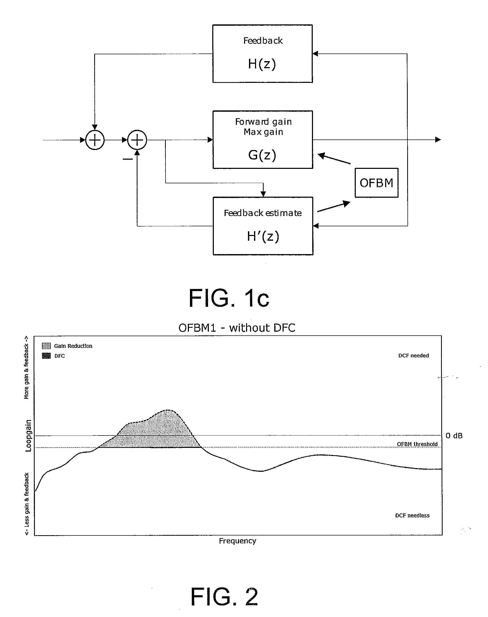
[0141]The OFBM1 is able to work as an (standalone) AFB system, if the target (predefined gain limit) for the OFBM1 is <0 dB loop gain and the system has a relatively fast update speed of e.g. 100 ms (i.e. an update frequency around 10 Hz). The closer the target loop gain is to 0 dB the faster a system is needed (the higher the update frequency). If the target is below 0 dB loop gain, the DFC system can be bypassed and only used for estimating the feedback path (cf. FIG. 2).

[0142]FIG. 2 shows a loop gain vs. normalized frequency curve for a hearing aid according to an embodiment of the invention comprising an online feedback manager unit OFBM1 used as an AFB system without a dedicated DFC system. The normalized frequency range corresponds to a real frequency range of e.g. 20 Hz to 12 kHz. The OFBM1 system uses the feedback estimate to control the maximum gain of the feedback loop. The DFC is not needed, because the fe...

example 2

OFBM2, Use of an (Relatively Fast) OFBM as a Feedback Limiter

[0148]The OFBM can be used to limit the maximum loop gain. The working interval for the DFC system is from −∞ dB to +∞ dB loop gain. This interval is difficult to handle, and it is well known that a working interval from about 0 dB to 12 dB loop gain is the optimum for the DFC system. Using the OFBM to limit the maximum loop gain ensures that the DFC system will not be pushed too much: If the loop gain increases above the limit (predefined gain limit), the forward gain will be reduced and thus increase the ability for the DFC system to remove the feedback. This can be seen as changing the working interval for the DFC from −∞ dB to +∞ dB loop gain to e.g.−∞ dB to a predefined gain limit, here +12 dB loop gain (cf. FIG. 4). FIG. 4 shows a loop gain vs. normalized frequency curve for a hearing aid according to an embodiment of the invention comprising an online feedback manager unit OFBM2 used as feedback limiter. If the loop...

example 3

OFBM3, Use of an (Relatively Slow) OFBM as a Feedback Optimizer

[0152]The OFBM3 can be seen as an adaptive addition to the initial max gain IGmax set during an initial (or later) fitting procedure (e.g. by an audiologist). It is known that the feedback path will change over time as a result of the different conditions through the day or days. The target of the OFBM3 is to slowly update the max gain to follow these changes.

[0153]If the max gain is too low, the user has less gain than wanted and the DFC system has problems estimating the feedback path (cf. FIG. 5). FIG. 5 shows a loop gain vs. normalized frequency curve for a hearing aid according to an embodiment of the invention comprising an online feedback manager unit OFBM3 used as feedback optimizer in a case of too low maximum gain. The maximum gain is too restrictive, so the user might not get the wanted gain.

[0154]If max gain IGmax is too high, it will be more difficult for the DFC system to handle quick and large increases in...


PUM

PropertyMeasurementUnit
frequencyaaaaaaaaaa
frequencyaaaaaaaaaa
frequencyaaaaaaaaaa

Abstract

The invention relates to a hearing aid system comprising an input transducer, a forward path, an output transducer and an electrical feedback path, the forward path comprising a signal processing unit for modifying an electrical input signal to a specific hearing profile over a predefined frequency range, wherein the predefined frequency range comprises a number of frequency bands, for which maximum forward gain values IGmax for each band can be stored in a memory, the electrical feedback path comprising an adaptive filter for estimating acoustical feedback from the output to the input transducer. The invention further relates to a method of adapting a hearing aid system to varying acoustical input signals. The object of the present invention is to provide an alternative acoustic feedback compensation scheme. The object is fulfilled in that the hearing aid system further comprises an online feedback manager unit for—with a predefined update frequency—identifying current feedback gain in each frequency band of the feedback path, and for subsequently adapting the maximum forward gain values in each of the frequency bands in dependence thereof in accordance with a predefined scheme. This has the advantage of providing a diminished probability for disturbing feedback improved feedback cancellation. The invention may e.g. be used in digital hearing aids for use in a variety of acoustical environments.

Description

TECHNICAL FIELD[0001]The invention relates to feedback compensation in a hearing aid system comprising a feedback path with an adaptive filter for estimating acoustical feedback from an output transducer to an input transducer of the hearing aid system. The invention furthermore relates to a method of adapting a hearing aid system to varying acoustical input signals, and to a method of manufacturing a hearing aid system.[0002]The invention may e.g. be useful in digital hearing aids for use in a variety of acoustical environments.BACKGROUND ART[0003]It is a well known problem that a hearing aid can become unstable and howl when loop gain exceeds 1. The (open) loop gain is a product of the gain in the hearing aid and the coupling between the receiver (speaker) and microphone, primarily, but not exclusively, through a vent in the earpiece. The vent is generally inserted in the earpiece of hearing aids so as to avoid occlusion. The coupling between the receiver and microphone is called ...

Claims


Application Information

Patent Timeline
Patent Type & Authority Applications(United States)
IPC IPC(8): H04R25/00H04R31/00
CPCH04R25/453H04R25/505Y10T29/49005H04R25/554H04R2430/03H04R25/552
Inventor BOLDT, JESPER BUNSOW
Owner OTICON
Why Eureka
Try Eureka