Pressure control valve device

a technology of pressure control valve and valve body, which is applied in the direction of fluid pressure control, process and machine control, instruments, etc., can solve the problems of increasing the hydraulic resistance adversely affecting the valve dynamics, and increasing production costs to an undesired extent, so as to reduce the risk of seat bounce, reduce production costs, and facilitate assembly

Active Publication Date: 2010-11-04
ZF FRIEDRICHSHAFEN AG
View PDF16 Cites 21 Cited by
  • Summary
  • Abstract
  • Description
  • Claims
  • Application Information

AI Technical Summary

Benefits of technology

[0026]In other advantageous embodiments of the pressure control valve device according to the invention, sufficient damping of pressure fluctuations at the same time as low through-flow resistance is achieved if the diametrically tapering section of the nozzle area is followed by an at least approximately hollow-cylindrical transition zone, followed in turn by an optional diffuser which merges into the second valve seat, since the hydraulic fluid flow lines guided along the walls in the nozzle area can undergo further, smooth deflections without influencing the twisting or vortex-like flow, and pressure fluctuations can thus be damped further without appreciably increasing the through-flow resistance.
[0027]In an embodiment of the pressure control valve device that can be produced inexpensively and is technologically simple to make, the nozzle area and the part of the flow guide device comprising the channel areas are made from different materials, and in a further embodiment of the pressure control valve device which is simple to assemble, the nozzle section and the part of the flow guide device with the channels can preferably be joined to one another by a clip connection.
[0028]In an advantageous further development of the pressure control valve device according to the invention, the fluid flows through the valve seat of the second poppet valve at least approximately in the tangential plane of an area of a sealing surface of a valve closure element that co-operates with the second valve seat, whereby the risk of seat-bounce in the area of the second poppet valve is reduced considerably and both an outflow with lower losses in the area of the valve seat, and good dynamics of the pressure control valve device are achieved, especially at low operating temperatures of the hydraulic fluid.
[0029]An embodiment of the pressure control valve device which ensures its correct function in a simply designed manner is characterized in that a valve tappet in active connection with the valve closure element is guided to move longitudinally in the area of the part of the flow guide device comprising the channel areas, since in this way transverse forces acting on the valve tappet can in a simple manner be supported in that area by a plurality of support points separated from one another and the tilting and oblique positioning of the valve tappet, which impair its mobility, are avoided.
[0030]In a further advantageous design of the pressure control valve device according to the invention, the first poppet valve is made with a ball seat and a diaphragm forming the valve seat has a thickness smaller that 0.4 mm and preferably smaller than 0.3 mm, whereby, compared with conventionally made pressure control valve devices, the spread of the volume flow over the temperature range is reduced and the temperature dependence of the valve characteristic is decreased.
[0031]If the second poppet valve is made with a conical seat, then for the same control pressure, compared with a ball seat or a flat seat the valve closure element that co-operates with the valve seat has a larger opening stroke, so that compared with a ball seat or flat seat the helical effect of the hydraulic fluid flow that improves the valve dynamics is further enhanced. In addition, in the case of a poppet valve made with a conical seat the flow of the hydraulic fluid can take place tangentially to the seat surface of the second poppet valve with lower through-flow resistance.

Problems solved by technology

The flow guide element deflects the hydraulic fluid flowing between the two poppet valves in some sections away from the direct flow path, in order to avoid Venturi effects between the poppet valves and the connection to the consumer, but this defined flow guiding increases the hydraulic resistance to an undesired extent and has an adverse effect on the valve dynamics.
However, closed-end pressure regulators made with damping elements are disadvantageously characterized by high design complexity so that, compared with pressure regulators made without a damping element, their production costs increase to an undesired extent.
In the design of the closed-end pressure regulators described above, the requirements for good control dynamics at the same time as low leakage constitute conflicting demands which can only be resolved by the acceptance of compromises.
At low oil temperatures, because of the higher viscosity of the hydraulic fluid, the above-described closed-end pressure regulators have a greatly reduced inlet volume flow, which adversely affects the valve dynamics in particular of pilot-pressure-controlled clutch valves.
However, compensation of this temperature-dependent valve dynamics impairment by a larger inlet geometry of the closed-end pressure regulator is not, or is only partially expedient since then, at high hydraulic fluid temperatures, the closed-end pressure regulators have an undesirably large leakage volume flow.

Method used


Image

  • Pressure control valve device
  • Pressure control valve device
  • Pressure control valve device

Examples


Embodiment Construction

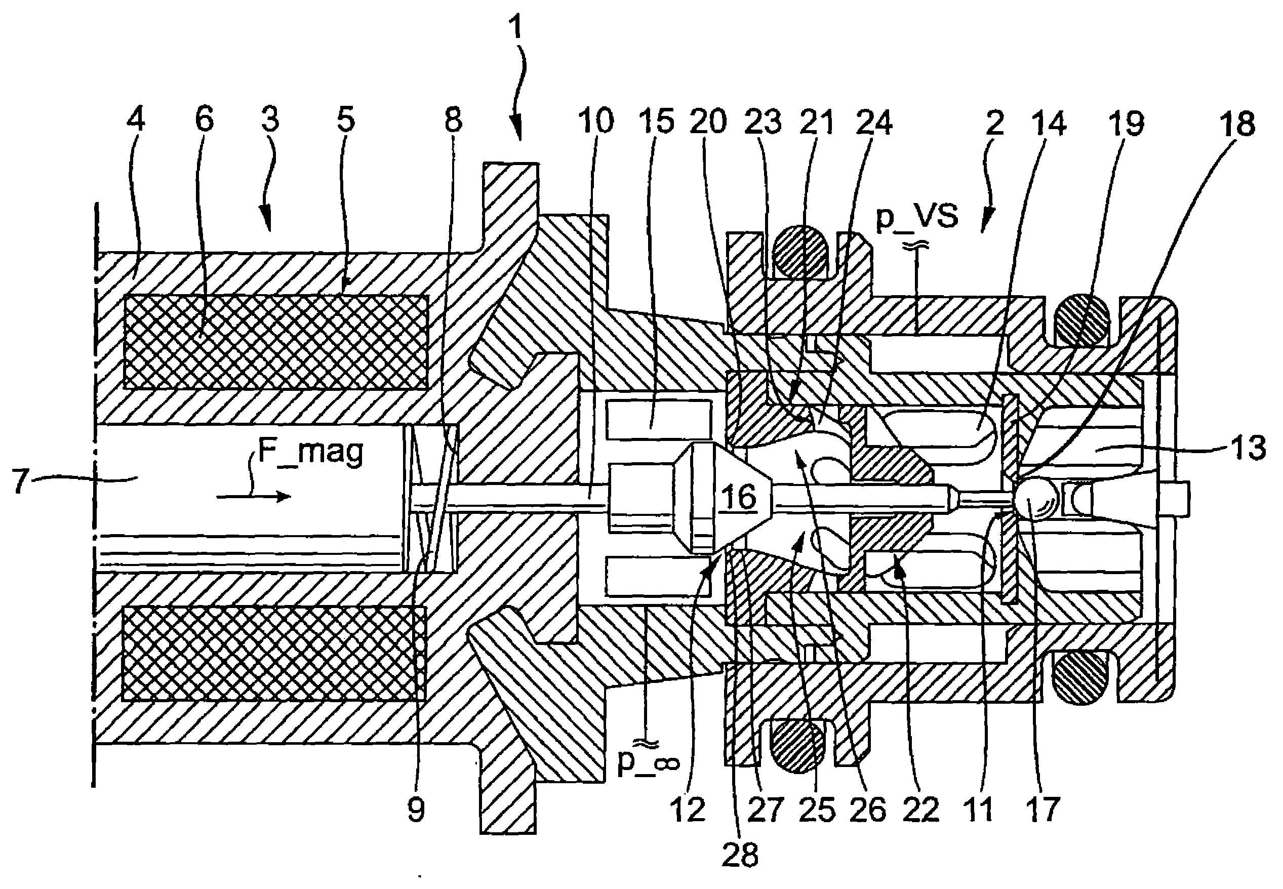
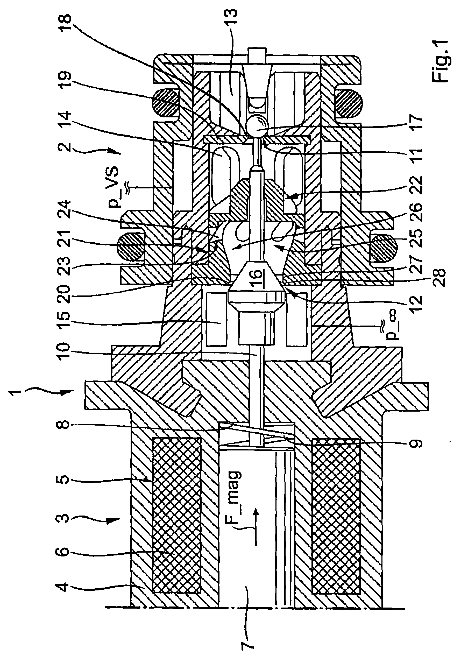
[0040]FIG. 1 shows schematically a longitudinally sectioned view of a pressure control valve device 1 of a hydraulic system for producing a required operating condition of a motor vehicle automatic transmission, which comprises a valve device 2 and an actor device 3 which actuates the valve device 2 in the manner described later. The pressure control valve device 1 represented in the drawing is designed as a pressure-limiting valve which can be actuated as a function of a pilot control pressure adjusted by another pressure control valve of the hydraulic system, and by means of which an actuating pressure can be produced for a shifting element such as a disk clutch or disk brake.

[0041]The actor device 3 of the pressure control valve device 1 comprises in a housing 4 a proportional magnet 5 whose coil 6, in the energized condition, acts upon an armature 7 with a magnetic force F_mag and displaces it from the position shown in FIG. 1, against the spring force of a spring device 9, in t...


PUM


Abstract

A pressure control valve device with at least one inlet area and first and second outlet areas which can be connected by two poppet valves. A flow guide device (21), with inflow and outflow areas (22, 23) for guiding the fluid flowing from the inlet area in a defined manner in the direction of the second poppet valve, is located upstream of the second poppet valve, between the first and second outlet areas. The fluid in the flow guide device (21) passes in the area between the inflow and outflow areas (22, 23) through a plurality of channel areas distributed around the periphery of the flow guide device (21) and separated from one another, which are shaped at least approximately helically and impart an at least approximately vortex-like flow pattern to the fluid flowing in the direction of the second poppet valve downstream of the outflow area (23).

Description

[0001]This application is a National Stage completion of PCT / EP2008 / 066983 filed Dec. 8, 2008, which claims priority from German patent application serial no. 10 2008 000 106.6 filed Jan. 21, 2008.FIELD OF THE INVENTION[0002]The invention concerns a pressure control valve.BACKGROUND OF THE INVENTION[0003]In motor vehicle automatic transmissions known from practice, shifting elements in the form of wet-operating disk clutches or disk brakes are used to transfer torque between a transmission input and a transmission output. In this context, force is transferred by frictional means, by the compression of disk sets of the shifting elements. The pressing force required in each case for this compression of the disk sets is usually produced by hydraulically actuated clutch pistons, which are actuated by means of pressure control valves and clutch valves. Such clutch valves, also known as pressure-reduction valves, are appropriately actuated either directly by a proportional magnet, or by f...

Claims


Application Information

Patent Timeline
Patent Type & Authority Applications(United States)
IPC IPC(8): G05D16/04
CPCF16D48/02F16D2048/0221F16D2500/1027G05D16/2013F16D2500/70406F16K31/0634F16D2500/3022G05D16/2024Y10T137/87217Y10T137/86622Y10T137/87917
Inventor MOOSMANN, MARKUSHAMMA, FRANKMAYR, KARLHEINZREMMLINGER, HUBERT
Owner ZF FRIEDRICHSHAFEN AG
Why Eureka
Try Eureka