Eureka AIR delivers breakthrough ideas for toughest innovation challenges, trusted by R&D personnel around the world.

Systems and methods for photo-mechanical hearing transduction

a technology of photo-mechanical and sound transduction, applied in the direction of optical signal transducers, implantable hearing aids, ear supported sets, etc., can solve the problem of mechanical or electrical failure of the connection between the light transmission component and the output transducer assembly

Active Publication Date: 2011-01-11
EARLENS CORP
View PDF234 Cites 88 Cited by
  • Summary
  • Abstract
  • Description
  • Claims
  • Application Information

AI Technical Summary

Benefits of technology

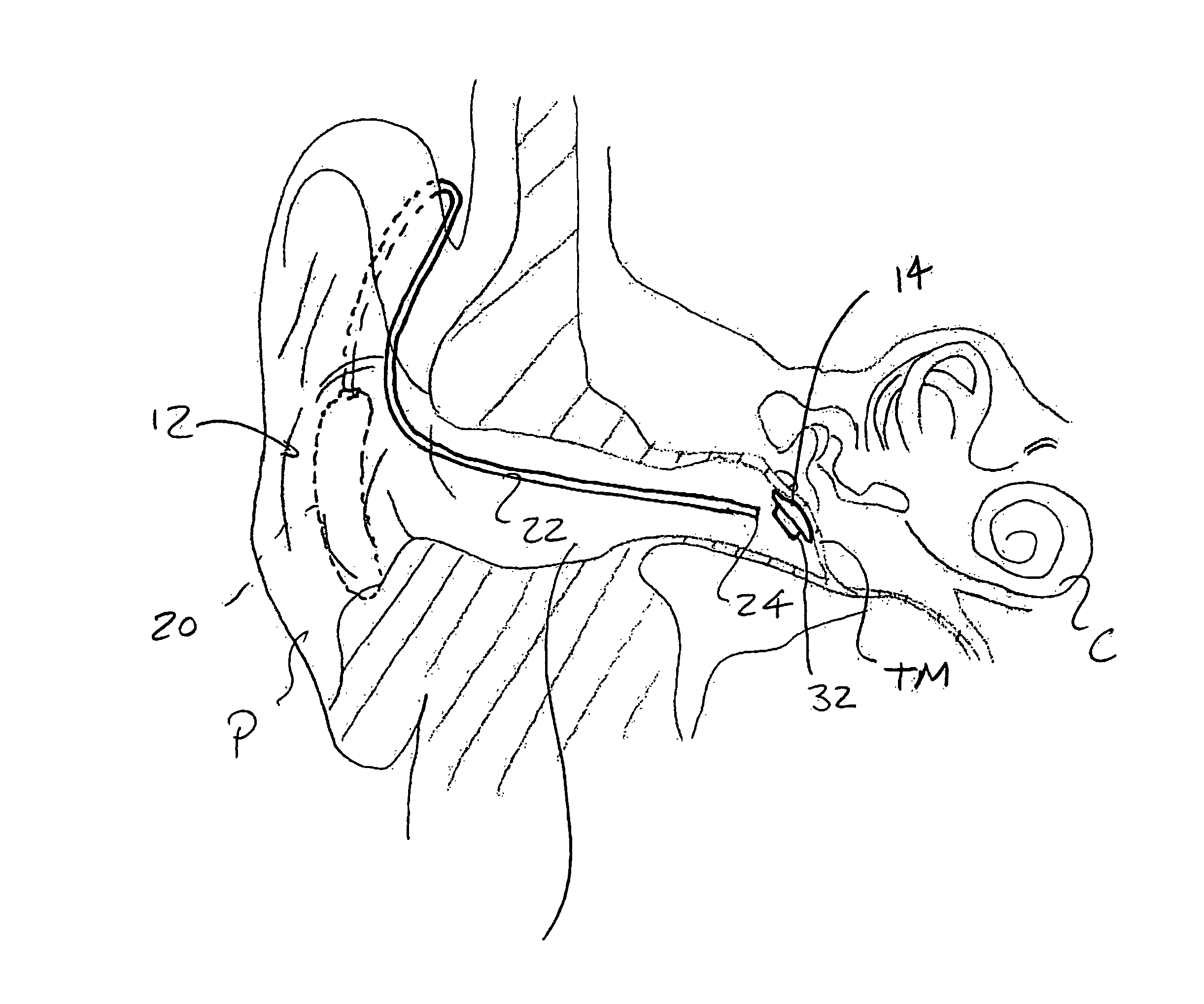
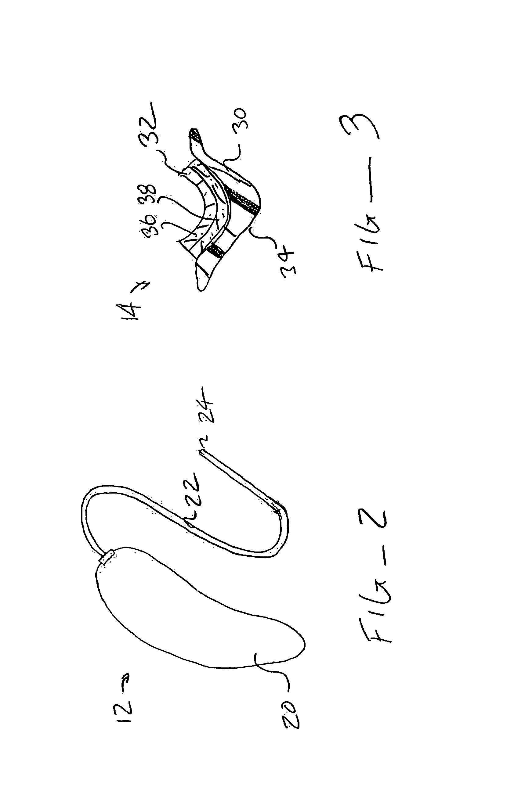
The present invention provides improved systems and methods for inducing neural impulses in the hearing transduction pathway of a human subject. The systems include an input transducer assembly and an output transducer assembly. The input transducer assembly converts ambient sound into a light signal, which is then converted into a mechanical vibration by the output transducer assembly. The output transducer assembly is designed to induce neural impulses on the tympanic membrane, which can be used as sound by the subject. The input transducer assembly can be a hearing aid or an ear piece, and it can be worn behind the pinna or implanted within the middle ear. The light transmission between the input and output transducers is not dependent on the exact position between them, which reduces the need for tight tolerances in the overall system and simplifies the insertion and removal of the input transducer. The output transducer assembly can be permanently or reversibly attached to the eardrum or the side of the malleus bone in contact with the tympanic membrane. The input transducer assembly can be connected to other electronic sources or components using wireless links or wired connections. The design and construction of the output transducer assembly is well described in prior U.S. Pat. No. 5,259,032.

Problems solved by technology

Additionally, there is no connection between the light transmission component and the output transducer assembly which is subject to mechanical or electrical failure.

Method used


Image

  • Systems and methods for photo-mechanical hearing transduction
  • Systems and methods for photo-mechanical hearing transduction
  • Systems and methods for photo-mechanical hearing transduction

Examples


Embodiment Construction

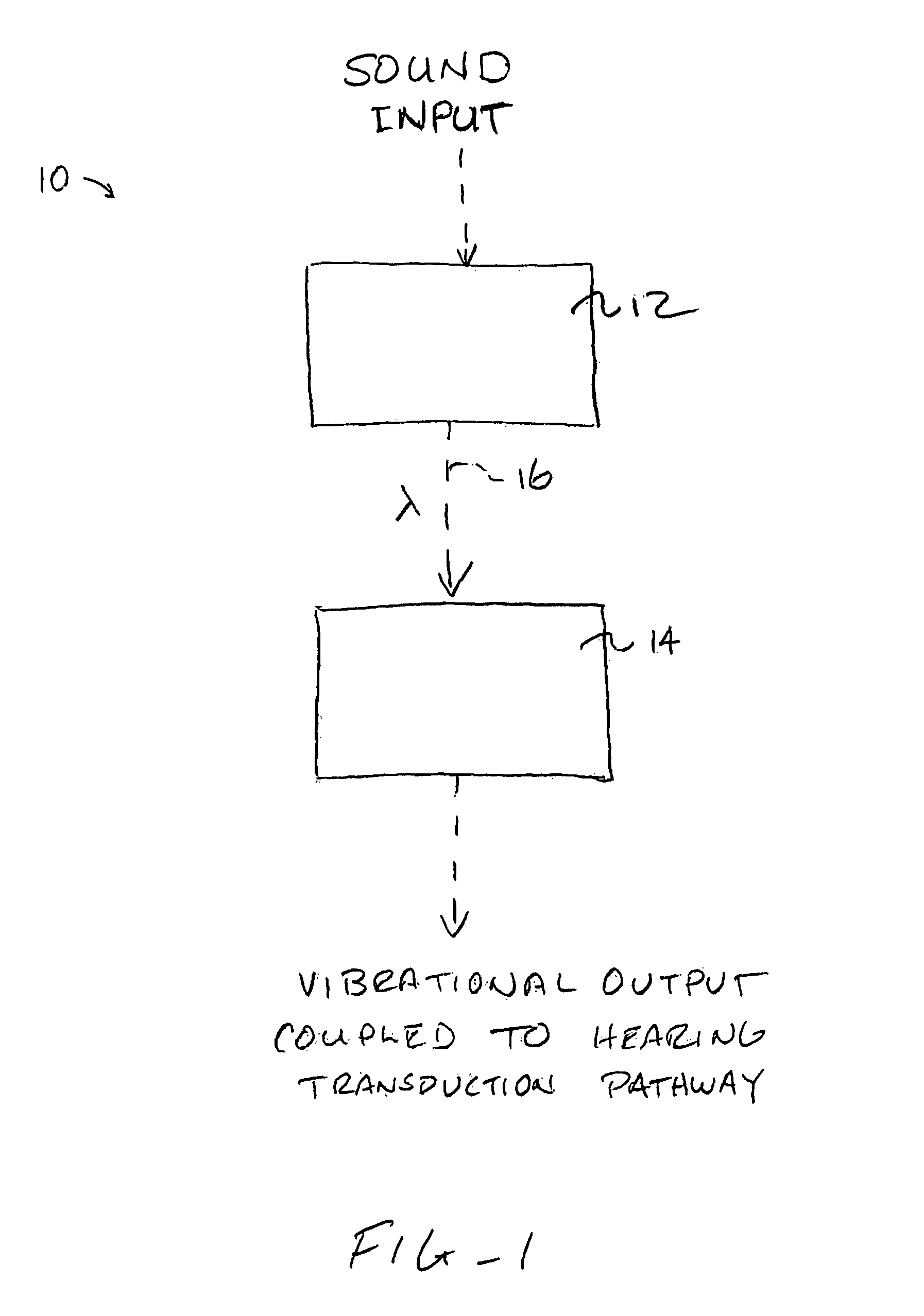
[0050]As shown schematically in FIG. 1, systems 10 constructed in accordance with the principles of the present invention will comprise an input transducer assembly 12 and an output transducer assembly 14. The input transducer assembly 12 will receive a sound input, typically either ambient sound (in the case of hearing aids for hearing impaired individuals) or an electronic sound signal from a sound producing or receiving device, such as the telephone, a cellular telephone, a radio, a digital audio unit, or any one of a wide variety of other telecommunication and / or entertainment devices. The input transducer assembly will produce a light output 16 which is modulated in some way, typically in intensity, to represent or encode a “light” sound signal which represents the sound input. The exact nature of the light input will be selected to couple to the output transducer assembly to provide both the power and the signal so that the output transducer assembly can produce mechanical vib...


PUM


Abstract

Hearing systems for both hearing impaired and normal hearing subjects comprise an input transducer and a separate output transducer. The input transducer will include a light source for generating a light signal in response to either ambient sound or an external electronic sound signal. The output transducer will comprise a light-responsive transducer component which is adapted to receive light from the input transducer. The output transducer component will vibrate in response to the light input and produce vibrations in a component of a subject's hearing transduction pathway, such as the tympanic membrane, a bone in the ossicular chain, or directly on the cochlea, in order to produce neural signals representative of the original sound.

Description

CROSS-REFERENCES TO RELATED APPLICATIONS[0001]The present application is a non-provisional of U.S. Patent Application Ser. No. 60 / 618,408, filed Oct. 12, 2004, the full disclosure of which is incorporated herein by reference.BACKGROUND OF THE INVENTION[0002]1. Field of the Invention[0003]The present invention relates generally to systems and methods for sound transduction. In particular, the present invention relates to the use of light signals for producing vibrational energy in a transduction pathway from a subject's tympanic membrane to the subject's cochlea.[0004]A wide variety of hearing aids and ear pieces have been produced over the years to provide sound directly into a subject's ear. Most such hearing systems rely on acoustic transducers that produce amplified sound waves which impart vibrations directly to the tympanic membrane or ear drum of the subject. Hearing aids generally have a microphone component which converts ambient sounds into electrical signals which are then...

Claims


Application Information

Patent Timeline
Patent Type & Authority Patents(United States)
IPC IPC(8): H04R25/00H04R25/02
CPCH04R23/008H04R25/554H04R25/606H04R2225/67H04R2225/023
Inventor PLUVINAGE, VINCENTPERKINS, RODNEY C.
Owner EARLENS CORP
Why Eureka
Eureka Blog
Learn More