
H clip

a clip and h-shaped technology, applied in the field of clips, can solve the problems of falling off the material, difficult installation of conventional h-clips, and inconvenient insertion of h-clips, etc., and achieve the effects of convenient side-sliding, quick and easy insertion, and improved spacing

Active Publication Date: 2006-08-10
M&O PRODS +1
View PDF8 Cites 33 Cited by
  • Summary
  • Abstract
  • Description
  • Claims
  • Application Information

AI Technical Summary

Benefits of technology

[0005] The invention is an H-shaped clip used to connect two pieces of building material such as plywood, roofing sheath, wafer board or other materials quickly, securely and easily.
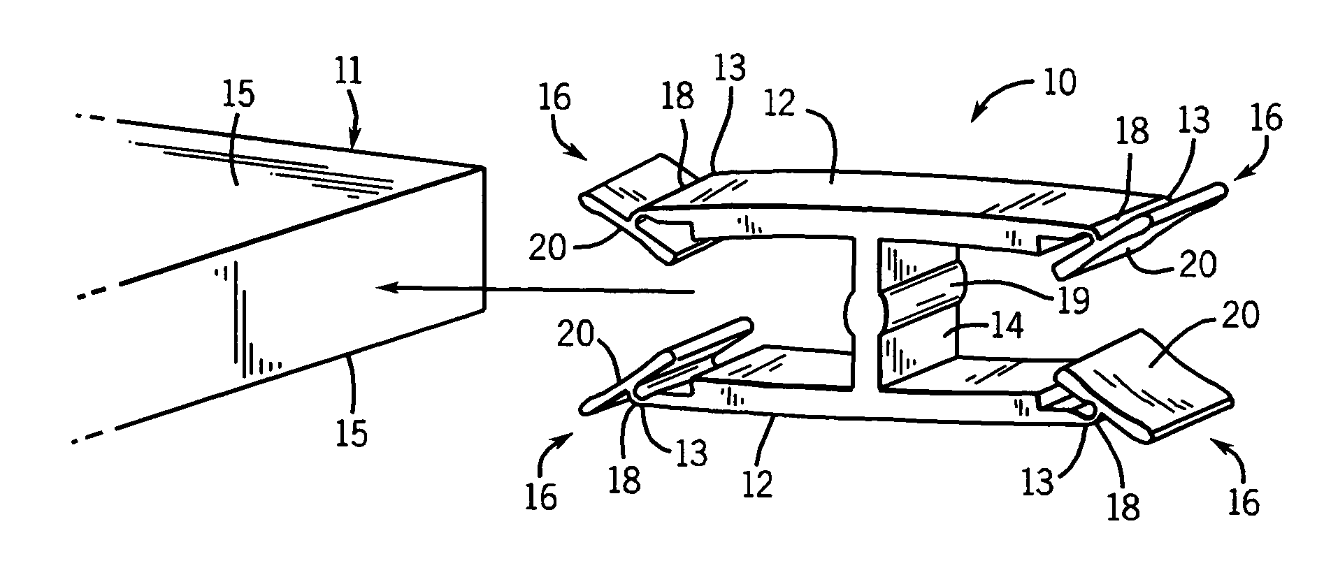
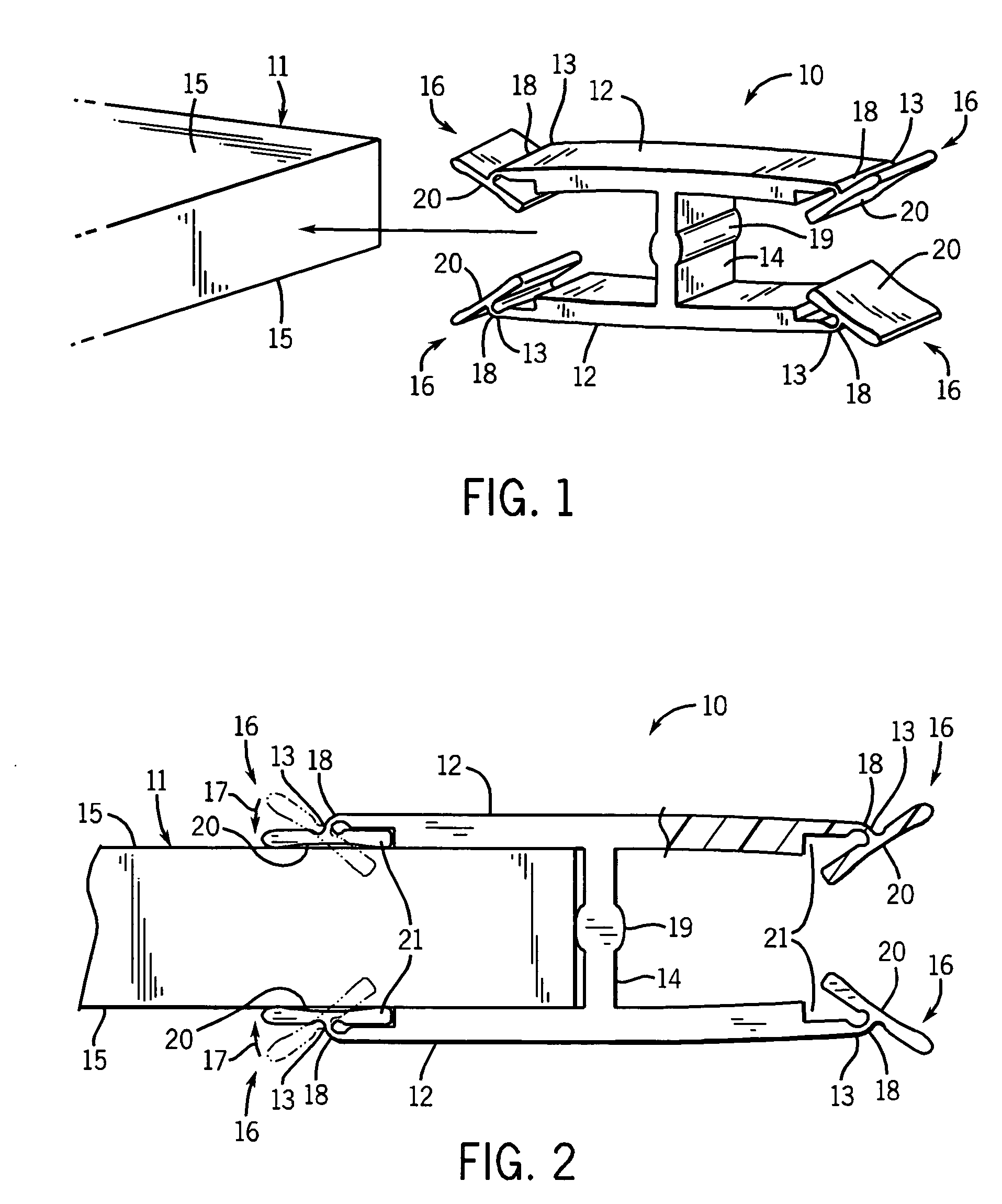
[0006] The H clip includes two opposed arms connected by a spacer bar, where each arm ends in a ski-shaped lead-in having a contoured face and a living hinge. The contoured face and living hinge provide the necessary flexibility to allow each ski-shaped lead-in to be quickly and easily inserted onto a piece of building material. Further, when the H clip is inserted between the materials, the contoured face of the lead-in helps to keep the H clip lying flat on the materials. Because the lead-in, living hinge, and tapered arms all work to grip the material, thereby keeping the H clip secured in position on the material, a second sheet of building material can be easily inserted into one or more of the H clips and easily slid sideways into its final position. The tapered arms allow the H clip to be used with materials of a variety of thicknesses.
[0007] In a preferred version, the H clip is made of a flexible material such as nylon, plastic or other polymeric compound that can adjust to a specified range of material thickness. Further, the H clip can be pre-loaded onto building materials and will stay in place. The H clip also provides better spacing between the building materials for expansion.
[0008] The H clip of the present invention has the advantages of fast and easy installation. In addition, the clip can be pre-loaded onto a sheet of building material and will stay in place. The H clips of the present invention allow for a consistent spacing, typically ⅛ inch space between the building material sheets.

Problems solved by technology

Thus, conventional H clips may be too tight or too loose for the given building material, and can often fall off the material.
Further, conventional H clips can be difficult to install.

Method used


Image

  • H clip
  • H clip
  • H clip

Examples


Embodiment Construction

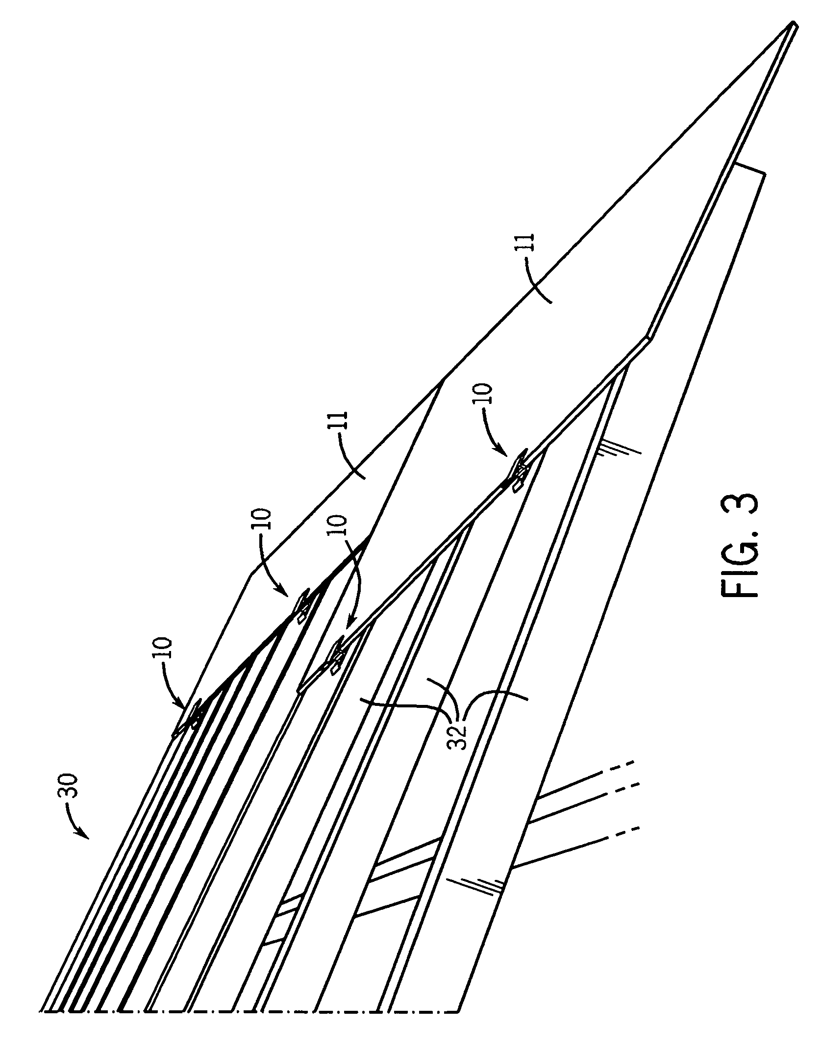
[0013] Referring now to FIGS. 1 and 2, the H clip 10 of the present invention is illustrated. The H clip 10 is used to connect two sheets of building material 11. The H clip 10 can be installed on a variety of building materials 11, such as plywood, roofing sheath, wafer board or other materials, quickly, easily and securely.

[0014] The H clip 10 is generally a one-piece unit which includes a pair of identical and opposed arms 12 in a modified parallel position to each other and connected by a spacing bar 14. Each arm 12 includes identical first and second ends 13. Preferably, the arms 12 are slightly tapered such that the distance between the arms 12 at ends 13 is closer than the distance between the arms 12 at the spacing bar 14. Therefore, the ends 13 of the arms 12 exhibit some resistance to a complete parallel relationship between the arms 12. In this manner, the tapered arms 12 allow the H clip 10 to be used with materials 11 of a variety of thicknesses.

[0015] The spacing bar...


PUM


Abstract

An H-shaped clip is used to connect two pieces of building material such as plywood, roofing sheath, wafer board or other materials quickly, easily and securely. The H clip includes two tapered arms connected by a spacing bar, where each arm ends in a ski-shaped lead-in having a contoured face and a living hinge.

Description

[0001] This utility patent application claims the benefit of Provisional Application No. U.S. 60 / 651,745 filed Feb. 10, 2005.FIELD OF THE INVENTION [0002] The present invention is directed to a clip for use in the construction industry and particularly to an H-shaped clip for spacing and installing building materials such as roof sheathing. BACKGROUND OF THE INVENTION [0003] In order for certain panel grades to be used at maximum support spacing, most building codes require that the edge of the panels be supported either by wood blocking, tongue and groove edges or panel clips. The construction and building industries use panel clips to fulfill this requirement. The clips are typically used to secure pieces of plywood or other sheets of wood together. Conventional clips are small, usually metal or galvanized clips formed in the shape of an “H” that fit between the joints of two pieces of building material, such as plywood or wafer board sheets, to stiffen the joint. Typically, H-sha...

Claims


Application Information

Patent Timeline
Patent Type & Authority Applications(United States)
IPC IPC(8): E04C3/02E04C3/00
CPCE04B1/6112E04D12/00E04F2201/0517Y10T24/44855F16B5/0008F16B5/0028Y10T24/344E04F2201/0594
Inventor MATSON, JOHN R.
Owner M&O PRODS
Learn More