Multilayer piezoelectric motor

a piezoelectric motor and multi-layer technology, applied in piezoelectric/electrostrictive/magnetostrictive devices, piezoelectric/electrostriction/magnetostriction machines, electrical apparatus, etc., can solve the problems of accelerating deterioration of the structure of the micromotor, body often begins to move with an uncontrollable lurching, and achieves improved control, improved control, and improved control

Inactive Publication Date: 2006-08-10
NANOMOTION
View PDF23 Cites 26 Cited by
  • Summary
  • Abstract
  • Description
  • Claims
  • Application Information

AI Technical Summary

Benefits of technology

[0015] An aspect of some preferred embodiments of the present invention relates to providing a multilayer piezoelectric micromotor in which shear forces that stress bonds adhering layers together in the multilayer micromotor are substantially reduced.
[0029] Methods for providing accurate control of energy transfer to a moveable body from a piezoelectric motor by controlling longitudinal, transverse and / or bending vibrations independently of each other, in accordance with preferred embodiments of the present invention, have been described with respect to multilayer motors. However, these methods are applicable to and can be advantageous for operating any piezoelectric micromotor that enables longitudinal vibrations to be controlled independently of transverse and / or bending vibrations.

Problems solved by technology

Many of these types of “multilayer” micromotors cannot deliver the power and provide the speeds of the described piezoelectric micromotor.
In addition, during operation, shear forces often develop in the multilayer micromotor that stress bonds that hold layers of the micromotor together.
The shear forces tend to damage the bonds and often result in accelerated deterioration of the structure of the micromotor.
Whereas this type of multilayer micromotor can provide relatively large amounts of power at high speeds, substantial shear forces stress bonds that join plates in the stack.
The body therefore often begins to move with an uncontrollable lurching.
In addition, jitter of as much as a few milliseconds is common in the time at which the body begins to move after the micromotor is turned on.
A problem also sometimes exists when a piezoelectric motor is required to move a body from a first location and position it accurately at a second location.
It is generally difficult to control deceleration of the body as it approaches the second location with sufficient accuracy to bring the body directly to the second location so that it is accurately positioned at the second location.

Method used


Image

  • Multilayer piezoelectric motor
  • Multilayer piezoelectric motor
  • Multilayer piezoelectric motor

Examples


Embodiment Construction

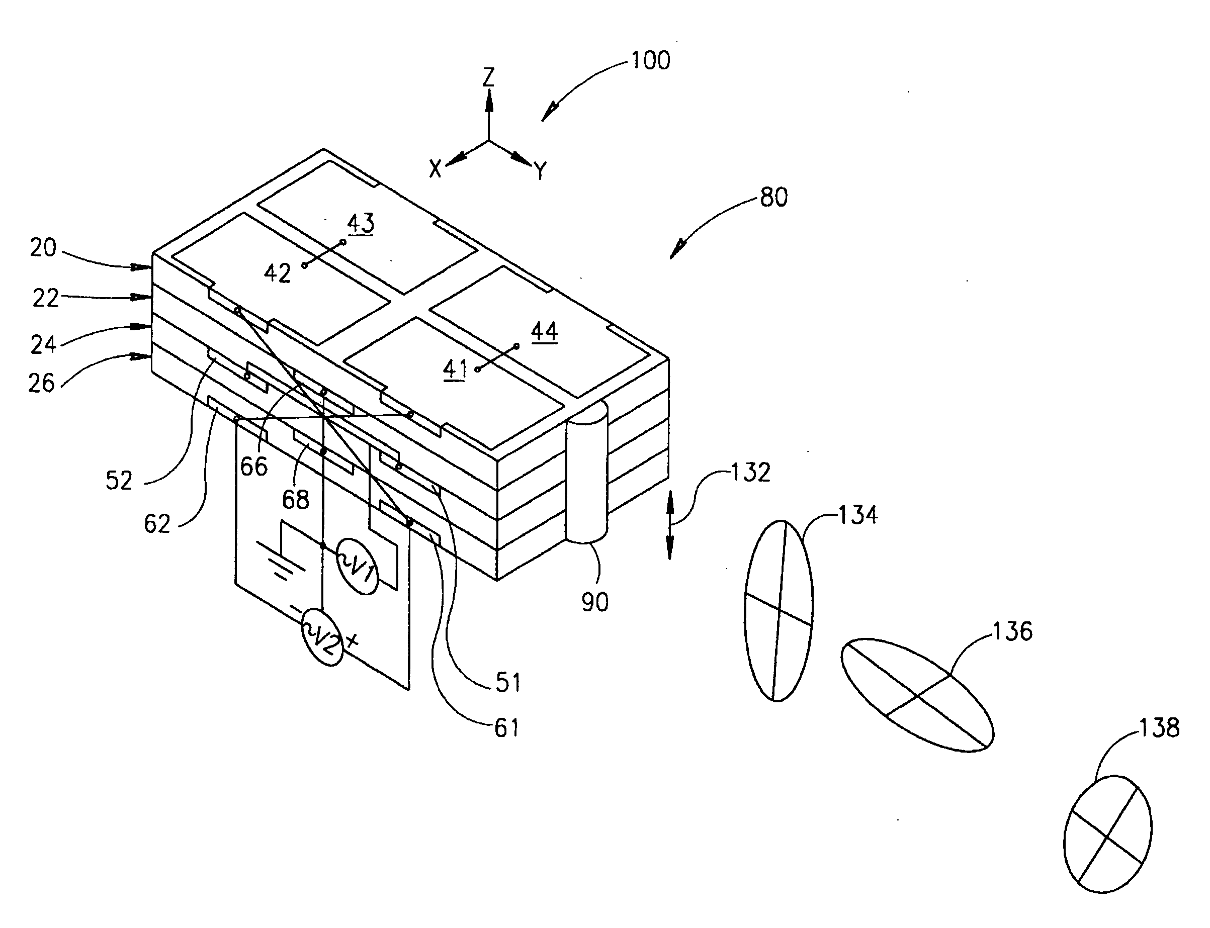
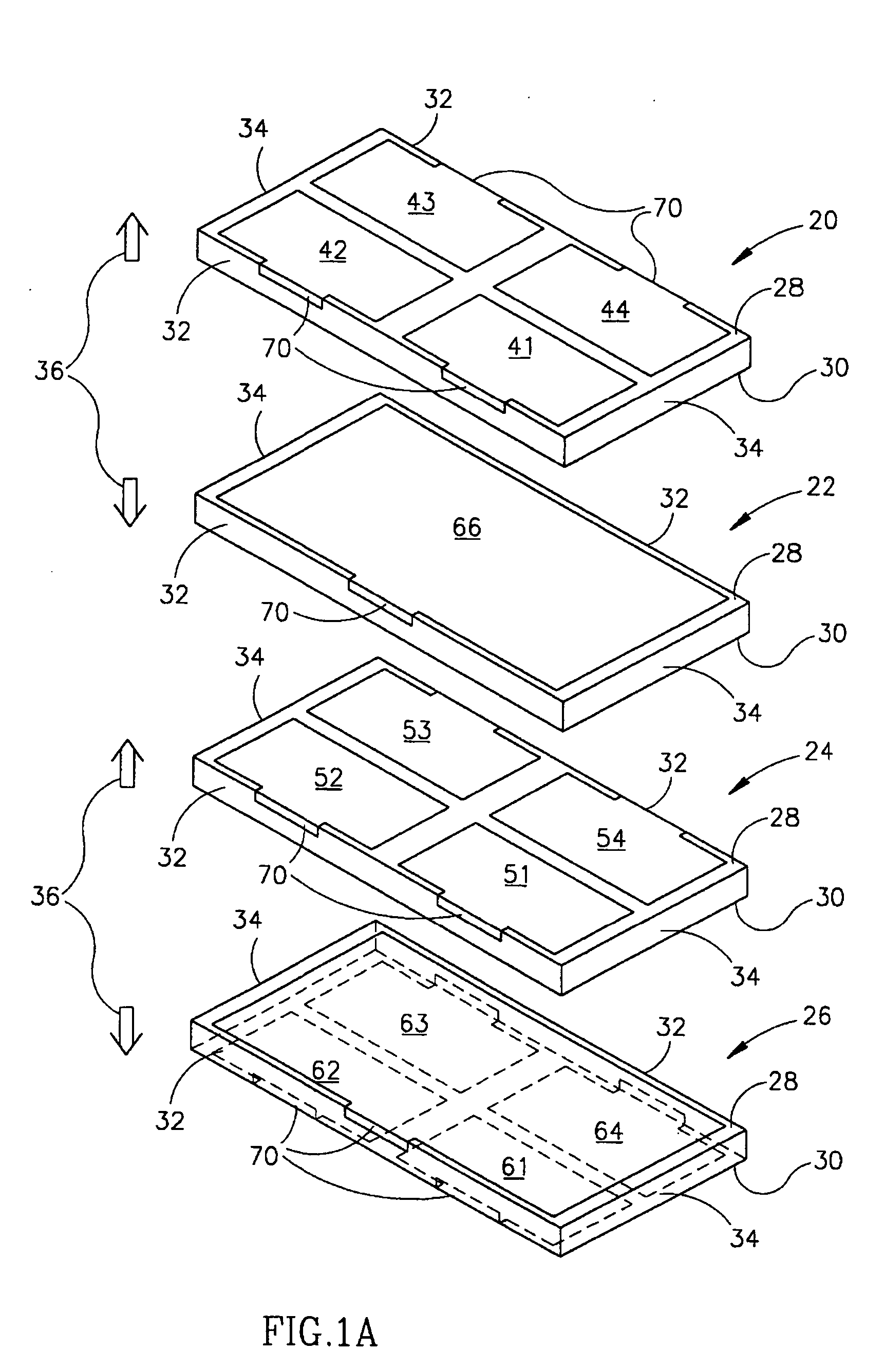
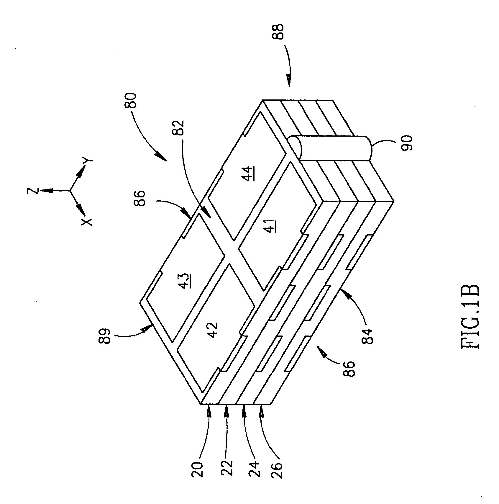
[0081]FIG. 1A shows schematically four thin piezoelectric layers 20, 22, 24 and 26 used to construct a multilayer micromotor, in accordance with a preferred embodiment of the present invention. The dimensions of layers 20, 22, 24 and 26 in FIG. 1A and elements and features shown in FIG. 1A and figures that follow are not necessarily to scale and are chosen for convenience of presentation. Furthermore, the choice of four layers in FIG. 1A is by way of example only and is not intended to imply a limitation of preferred embodiments of the present invention, which can have a number of layers other than four.

[0082] Each of layers 20, 22, 24 and 26 has relatively large parallel rectangular top and bottom surfaces 28 and 30 respectively, two narrow long edge surfaces 32 and two short edge surfaces 34. Bottom surface 30, a short edge surface 32 and a long edge surface 34 of each of layers 20, 22, 24 and 26 are hidden in the perspective of FIG. 1. Hidden edges of bottom surface 30 and elect...


PUM


Abstract

A method for accelerating or decelerating a moveable body which body is moved by urging a piezoelectric micromotor to the body in a first direction so that a contact region of the piezoelectric motor is pressed to the body and exciting vibrations in the piezoelectric micromotor at the contact region in the first direction and in a second direction along a direction of motion of the body, said vibrations having a first amplitude in the first direction and a second amplitude in the second direction, the method comprising: a) for acceleration, gradually changing a ratio between the second amplitude relative to the first amplitude from substantially zero to a desired non-zero value; or b) for deceleration, gradually changing the ratio between the second amplitude relative to the first amplitude from a non-zero value to substantially zero.

Description

RELATED APPLICATIONS [0001] The present application is a divisional of U.S. application Ser. No. 09 / 980,375, which was filed in the U.S. Patent and Trademark Office on Nov. 29, 2001 as a national application of PCT / IL99 / 00288, filed May 31, 1999.FIELD OF THE INVENTION [0002] The present invention relates to piezoelectric motors and in particular to multilayer piezoelectric motors formed from layers of piezoelectric material. BACKGROUND OF THE INVENTION [0003] Piezoelectric micromotors of different shapes and characteristics for driving moveable components of machines are well known in the art. U.S. Pat. No. 5,616,980, which is incorporated herein by reference, describes a piezoelectric micromotor capable of providing a relatively large amount of power for driving a moveable body. [0004] The piezoelectric micromotor comprises a thin rectangular piezoelectric plate having short and long edge surfaces and large parallel face surfaces. One of the large face surfaces has a single large e...

Claims


Application Information

Patent Timeline
Patent Type & Authority Applications(United States)
IPC IPC(8): H01L41/08H01L41/09H02N2/00H02N2/04
CPCH01L41/083H01L41/0913H02N2/004H02N2/0075H10N30/2023H10N30/50
Inventor GANOR, ZE'EVRAFAELI, IZHAKSHIV, LIORKARASIKOV, NIR
Owner NANOMOTION
Why Eureka
Try Eureka