Replacement of passive electrical components

a technology of electrical components and passive components, applied in the direction of printed resistor incorporation, printed capacitor incorporation, inking apparatus, etc., can solve the problems of inability to mount devices on internal layers, inability to produce well-defined features with good electrical properties, and inadequate approaches to da

Inactive Publication Date: 2006-08-10
CABOT CORP
View PDF90 Cites 64 Cited by
  • Summary
  • Abstract
  • Description
  • Claims
  • Application Information

AI Technical Summary

Benefits of technology

[0016] In another aspect, the invention provides a printed circuit comprising a substrate and a plurality of electrical components. At least one of the plurality of electrical components is physically mounted onto the substrate. At least one of the plurality of electrical components includes at least one electronic ink that is printed onto the substrate in a predetermined pattern using an ink-jet printing process. At least one of the plurality of electronic components may include at least two electronic inks that are printed onto the substrate in a predetermined pattern using an ink-jet printing process. The at least two electronic inks may be blended together prior to being cured. Alternatively, one of the at least two electronic inks may be cured prior to the other electronic ink being printed onto the substrate. The at least one electrical component that is printed onto the substrate using an ink-jet printing process may be selected from the group consisting of a conductor; a resistor; a capacitor; an inductor; a transistor; a dielectric; an insulator; a sensor; a diode; a keyboard; an input device; a relay; a switch; and a pixel. The at least one electrical component that is physically mounted onto the substrate may be selected from the group consisting of an integrated circuit, a high-precision resistor, a high-precision capacitor, an inductor, a transistor, an oscillator, a crystal, a connector, a sensor, an LED, a ferrite, a switch, a filter, a jumper, and a battery.
[0017] In yet another aspect of the invention, a process of constructing an electrical circuit is provided. The electrical circuit include...

Problems solved by technology

However, low viscosity compositions are not as well developed as the high viscosity compositions.
Ink-jet printing of conductors has been explored, but the approaches to date have ...

Method used


Image

  • Replacement of passive electrical components
  • Replacement of passive electrical components
  • Replacement of passive electrical components

Examples


Embodiment Construction

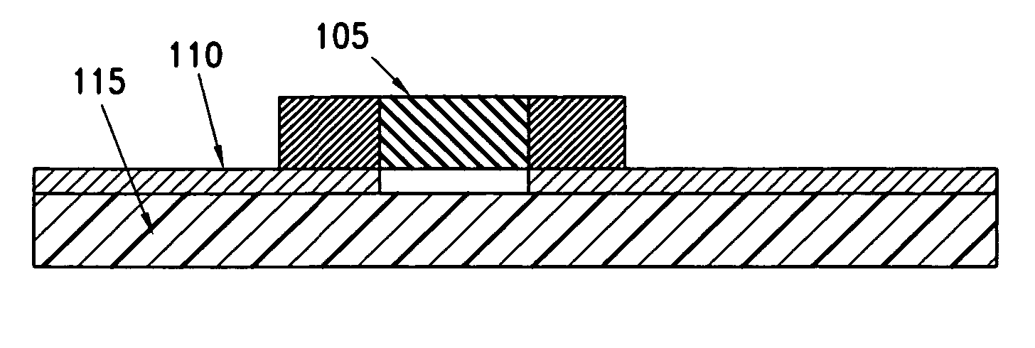
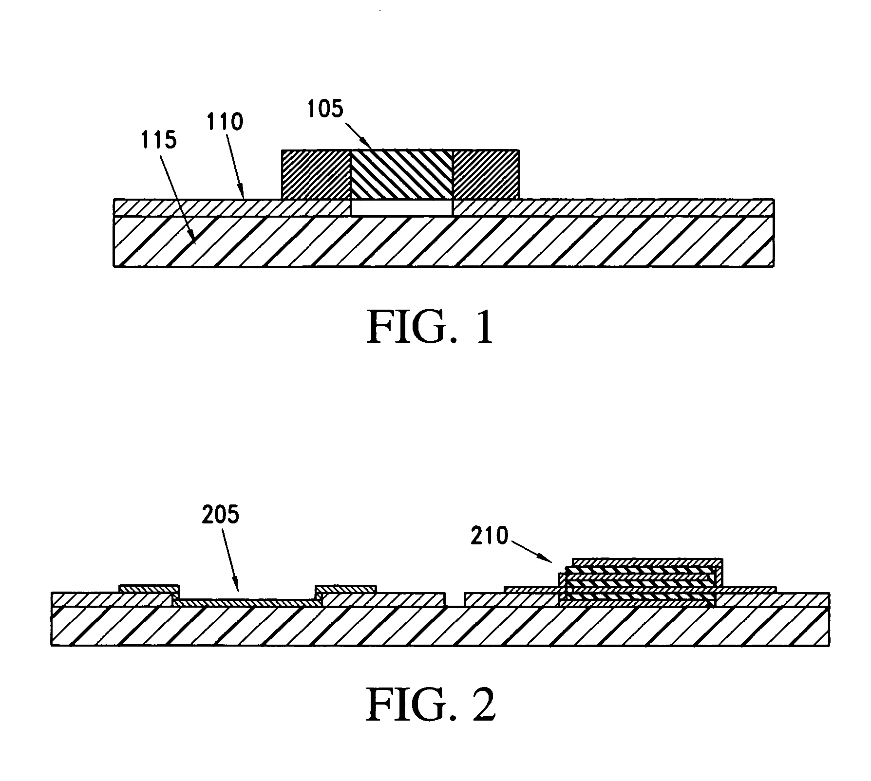
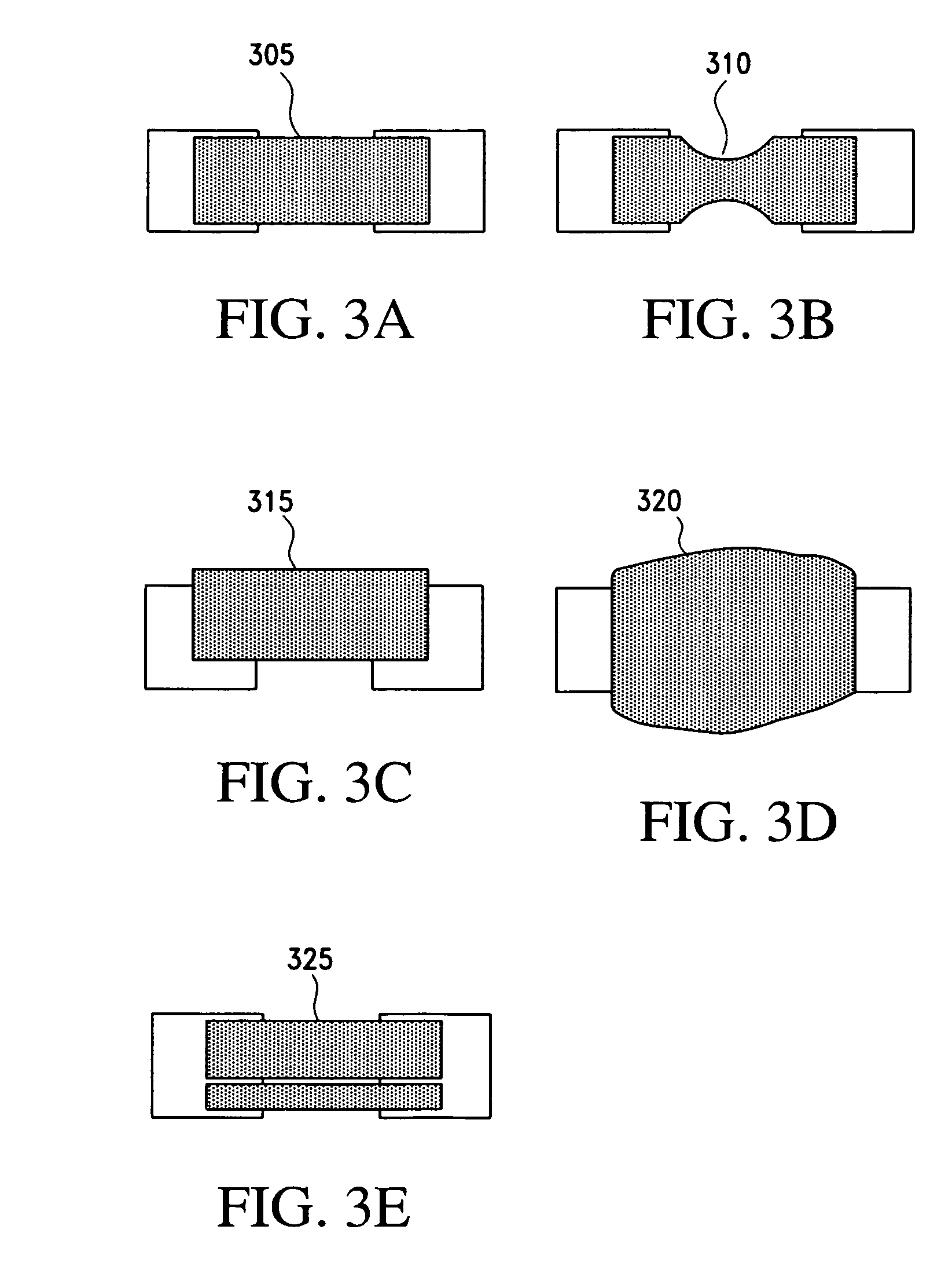
[0031] Ink jet deposition of different materials allows for replacement of standard Surface Mount (SMT) components that can be fabricated on the fly during the manufacturing process. Passive component fabrication via ink jet printing has an advantage over SMT technology in that components having a wide range of values can be deposited at any given time. In this manner, ink jet printing of components provides a direct advantage with respect to SMT technology, for which only discrete component values exist.

[0032] A second advantage provided by the fabrication of ink jet printable passive components according to the present invention, with respect to SMT discrete components, is the elimination of the need to stock SMT components. Conventional PCB manufacturers are typically required to stock vast quantities of different SMT components in order to keep the manufacturing line operating. If any one component becomes unavailable, the manufacturing line may be required to shut down until a...


PUM

PropertyMeasurementUnit
Electrical conductivityaaaaaaaaaa
Dielectric constantaaaaaaaaaa
Electrical resistivityaaaaaaaaaa

Abstract

A process of fabricating a passive electrical component, such as a resistor, a capacitor, or an inductor, is provided. The process includes the step of ink-jet printing at least one electronic ink onto a substrate in a predetermined pattern. The step of ink-jet printing may include the steps of: a) selecting at least one electronic ink having at least one electrical characteristic when cured; b) determining a positional layout for a plurality of droplets of the at least one electronic ink such that, when the at least one electronic ink has been cured, the positional layout provides a desired response for the electrical component; c) printing each of the plurality of droplets of the at least one electronic ink onto the substrate according to the positional layout using an ink-jet printing process; and d) curing the at least one electronic ink.

Description

CROSS-REFERENCE TO RELATED APPLICATIONS [0001] This application claims priority to U.S. Provisional Patent Application Ser. Nos. 60 / 643,577; 60 / 643,378; and 60 / 643,629, all filed on Jan. 14, 2005, the entireties of which are incorporated herein by reference. This application also claims priority to U.S. Provisional Patent Application Ser. No. 60 / 695,413, filed on Jul. 1, 2005, the entirety of which is incorporated herein by reference.BACKGROUND OF THE INVENTION [0002] 1. Field of the Invention [0003] The present invention relates to passive electrical components. More particularly, the invention relates to a method and apparatus for printing electrical components onto a substrate using electronic inks that, when cured, have electrical functionalities. [0004] 2. Related Art [0005] The electronics, display and energy industries rely on the formation of coatings and patterns of conductive materials to form circuits on organic and inorganic substrates. The primary methods for generating...

Claims


Application Information

Patent Timeline
IPC IPC(8): B41J2/01
CPCB41J2/01B41J2202/04H01C17/065H05K1/095H05K1/16H05K1/162H05K1/165H05K1/167H05K1/181H05K3/125H05K2201/09763H05K2203/013H05K2203/1453
Inventor HOWARTH, JAMES JOHNEDWARDS, CHUCKVANHEUSDEN, KAREL
Owner CABOT CORP
Why Eureka
Try Eureka