

Submersible lighting device
a lighting device and submerged technology, applied in the field of submerged lighting devices, can solve the problems of each having its own limitations, and achieve the effect of facilitating repair
- Summary
- Abstract
- Description
- Claims
- Application Information
AI Technical Summary
Benefits of technology
Problems solved by technology
Method used
Image

Examples
first embodiment
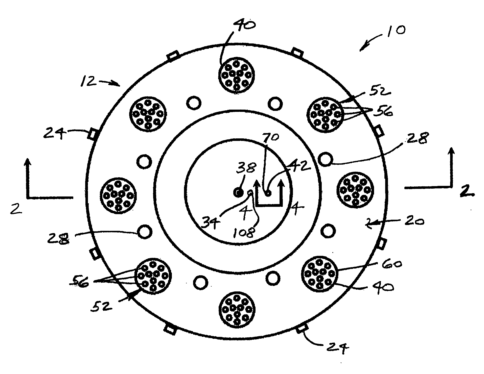
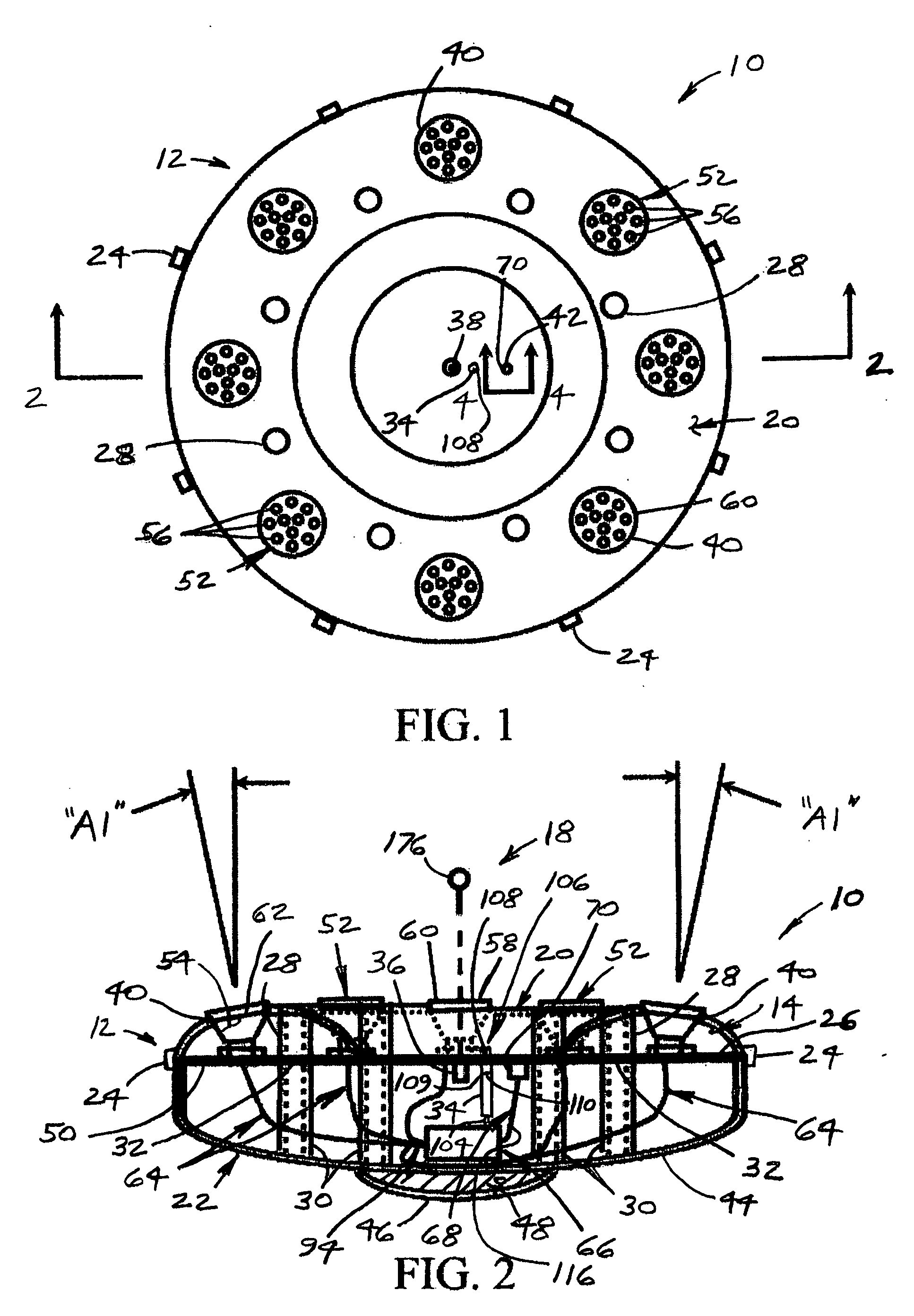
[0034]FIGS. 1 and 2 show the submersible lighting fixture or device, or more specifically the light ring, of the present invention, which is designated generally at 10. The device 10 includes a two-piece housing 12 of “inverted mushroom” shape that opens to permit access to component parts inside of that device 10. The device 10 further includes an electrical lighting system 14, a recharging device 16, and an optional lifting device 18.
[0035] The housing 12 is of a generally hollowed-out disk shape, preferably of about two feet in diameter. The housing 12 includes an upper housing half 20 and a lower housing half 22. The upper housing half 20 and the lower housing half 22 are sealed by a large rubber gasket 26.
[0036] The upper housing half 20, the lower housing half 22, and the large rubber gasket 26 are retained in sealing engagement using a plurality of clamps 24. The clamps 24 may be of (a) a spring type, such as those used on mason jars, luggage, or old-style cannister vacuum c...
second embodiment
[0061]FIGS. 8 and 9 depict a light ring 200, which includes a two-piece housing 202 that opens to access component parts of that housing 202. That housing 202 encloses the electrical lighting system 14, the recharging device 16, and an optional lifting device 204.
[0062] The housing 202 is of a generally hollowed disk shape, preferably about two feet in diameter, comprising an upper housing half 206 and a lower housing half 208. These two housing halves 206 and 208 are retained together in a sealing engagement, using a plurality of the clamps 24 to seal a large rubber gasket 210 between the housing halves 206 and 208.
[0063] A switch actuating tube 212 integral with the upper housing half 206 extends downwardly. The upper housing half 206 has an integral center U-bolt 214 to allow attachment of the lifting device 204. A plurality of light holes 216 extend through upper housing half 206. The lower housing half 208 has a flat lower surface 218 to which a weight disk 220 made of solid l...
third embodiment
[0071]FIGS. 10 and 11 show a light ring 236, which includes a two-piece housing 238 that opens to access component parts inside that housing 238, such as the electrical lighting system 14, and the recharging device 16.
[0072] The housing 238 is a generally hollow doughnut, having a life saving ring shape, preferably about two feet in diameter. Larger diameters are preferable, if the light ring 236 is used as a floatation device. This light ring 236 comprises an upper housing half 240 and a lower housing half 242 that are retained together in sealing engagement, using a plurality of clamps 24, with a large rubber gasket 244 sandwiched between the upper 240 and lower housing halves 242. The upper housing half 240 includes a center hole 246, defined by an inner side wall 248. A threaded electrical socket hole 250 extends through an outer side wall 252 of upper housing half 240. A switch actuating tube 254 integral with the upper housing half 240 extends radially inwardly. The upper hous...
PUM
 Abstract
Description
Claims
Application Information