Symbol timing recovery apparatus usable with VSB receiver and method thereof

Inactive Publication Date: 2006-08-10
SAMSUNG ELECTRONICS CO LTD
View PDF18 Cites 8 Cited by
  • Summary
  • Abstract
  • Description
  • Claims
  • Application Information

AI Technical Summary

Benefits of technology

[0024] Accordingly, the present general inventive concept provides a symbol timing recovery apparatus usable with a VSB receiver and a method thereof which recover symbol timing independently of a carrier re

Problems solved by technology

However, in the conventional symbol timing recovery apparatus using the upper band of the received signals, if the upper band is damaged, performance of the apparatus deteriorates.
Particularly, as multiple path components are in large quantities, the upper band is likely to be damaged.
As a result, in the re

Method used


Image

  • Symbol timing recovery apparatus usable with VSB receiver and method thereof
  • Symbol timing recovery apparatus usable with VSB receiver and method thereof
  • Symbol timing recovery apparatus usable with VSB receiver and method thereof

Examples


Example

[0055] Reference will now be made in detail to the embodiments of the present general inventive concept, examples of which are illustrated in the accompanying drawings, wherein like reference numerals refer to the like elements throughout. The embodiments are described below in order to explain the present general inventive concept by referring to the figures.

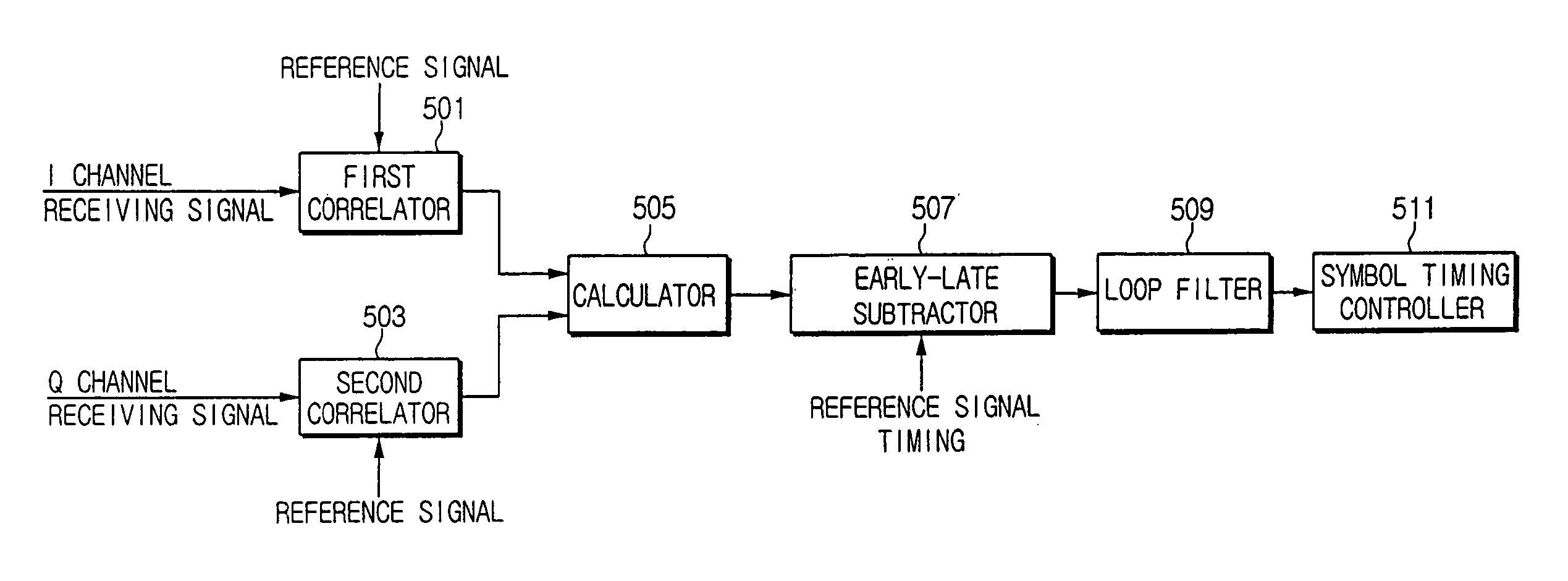
[0056]FIG. 5 is a block diagram illustrating a symbol timing recovery apparatus usable with a VSB receiver according to an embodiment of the present general inventive concept.

[0057] Referring to FIG. 5, the symbol timing recovery apparatus includes a first correlator 501, a second correlator 503, a calculator 505, an early-late subtractor 507, a loop filter 509, and a symbol timing controller 511. The symbol timing recovery apparatus performs a symbol timing recovery process using samples of an input signal. The input signal includes an I channel receiving signal and a Q channel receiving signal.

[0058] The first correlator 5...


PUM


Abstract

A symbol timing recovery apparatus usable with a VSB receiver, includes a first correlator to calculate a first correlation value between an I channel receiving signal and a timing recovery reference signal, a second correlator to calculate a second correlation value between a Q channel receiving signal having a phase difference of 90° with respect to the I channel receiving signal and the reference signal, a calculating member to calculate a non-coherent combining value based on the first correlation value output from the first correlator and the second correlation value output from the second correlator, an early-late subtractor to calculate a difference value between the non-coherent combing value of a previous sample and the non-coherent combing value of a subsequent sample in samples of the I and Q channel receiving signals, and to detect a symbol timing offset based on the calculated difference signal, and a symbol timing controller to control symbol timing based on the detected symbol timing offset. Accordingly, by using the non-coherent combining value of the first and second correlation values, it is possible to perform the symbol timing recovery regardless of carrier recovery error, thereby minimizing symbol timing jitter.

Description

CROSS-REFERENCE TO RELATED APPLICATIONS [0001] This application claims benefit under 35 U.S.C. § 119 from Korean Patent Application No. 2005-11401, filed on Feb. 7, 2005, in the Korean Patent Office, the disclosure of which is incorporated herein in its entirety. BACKGROUND OF THE INVENTION [0002] 1. Field of the Invention [0003] The present general inventive concept relates to a symbol timing recovery apparatus usable with a VSB receiver and method thereof, and more particularly, to a symbol timing recovery apparatus which usable with a VSB to recover symbol timing based on non-coherent combining of correlation values calculated using both an I channel receiving signal and a Q channel receiving signal. [0004] 2. Description of the Related Art [0005] In order to demodulate data in a data receiver device for receiving data transmitted by the Vestigial Side Band (VSB) signal modulation scheme, it is necessary to minimize the frequency offset and the phase noise generated by an RF osci...

Claims


Application Information

Patent Timeline
IPC IPC(8): H03D1/24H04L27/22
CPCH04L7/042H04L27/02A41D19/015A41D2500/40
Inventor LEE, DONG-HOON
Owner SAMSUNG ELECTRONICS CO LTD
Why Eureka
Try Eureka