Power tool system

a power tool and tool system technology, applied in the field of power tool systems, can solve the problems of requiring a rather cumbersome routine for setting the power tool, and achieve the effect of improving the anti-theft effect of the power tool

Active Publication Date: 2006-08-10
MATSUSHITA ELECTRIC WORKS LTD
View PDF10 Cites 56 Cited by
  • Summary
  • Abstract
  • Description
  • Claims
  • Application Information

AI Technical Summary

Benefits of technology

[0003] In view of the above problem, the present invention has been achieved to provide an antitheft power tool system which is capable of placing the power tool in security without resorting to any awkward setting. The power tool system in accordance with the present invention includes the power tool configured to include a controller which enables the power tool only upon receiving an authentication signal, and a wearable piece which is provided as a separate entity from the power tool and is configured to be worn by the user. The system includes a certification unit and an authenticator, one of which is incorporated in the wearable piece, and the other of which is incorporated in the power tool. The certification unit is configured to store an identification code specifying the power tool and to transmit the identification code. The authenticator is configured to read the identification code from the certification unit and to provide the authentication signal to the controller when the identification code is authenticated to be eligible for a privileged use of the power tool. Communication means is included in the system to establish a communication between the certification unit and the authenticator for transmission of the identification code, while the user holds the power tool with the wearable piece carried on. Accordingly, the power tool can be authenticated simply by the existence of the wearable piece on the user. Thus, the system can be free from any additional authentication procedure for preventing the unauthorized use of the power tool, giving an enhanced antitheft effectiveness to the power tool.

Problems solved by technology

However, it is required a rather cumbersome routine to set the power tool in security.

Method used


Image

  • Power tool system
  • Power tool system
  • Power tool system

Examples


Embodiment Construction

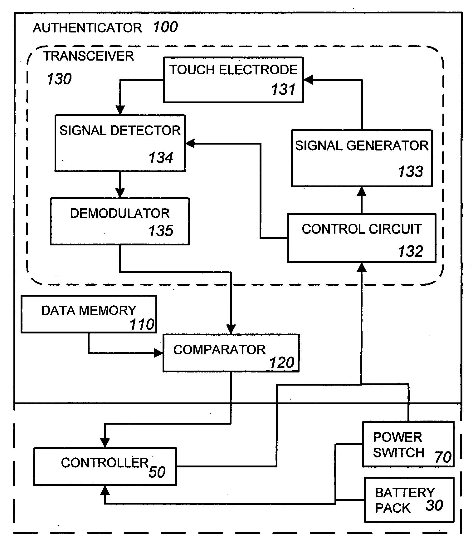
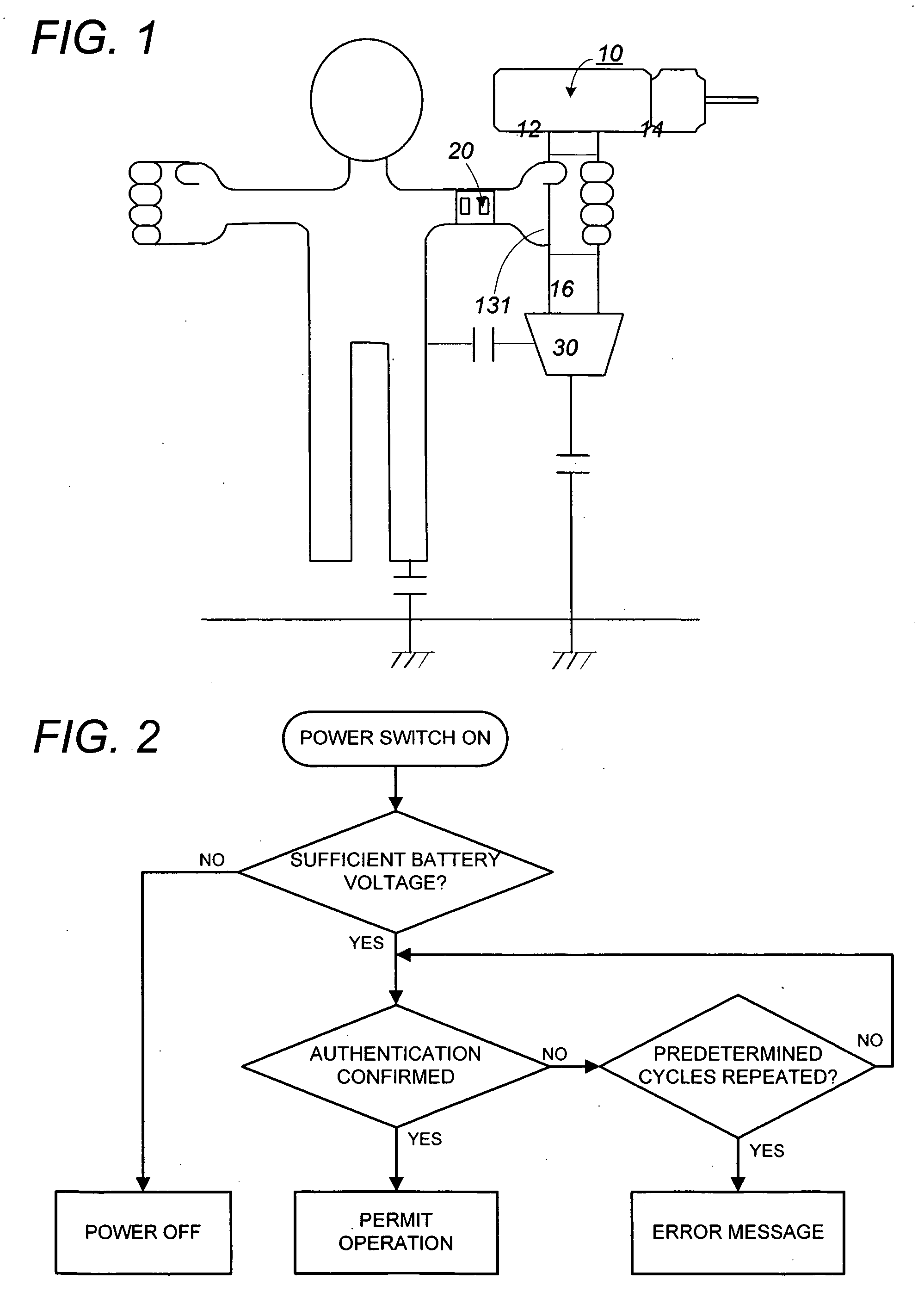
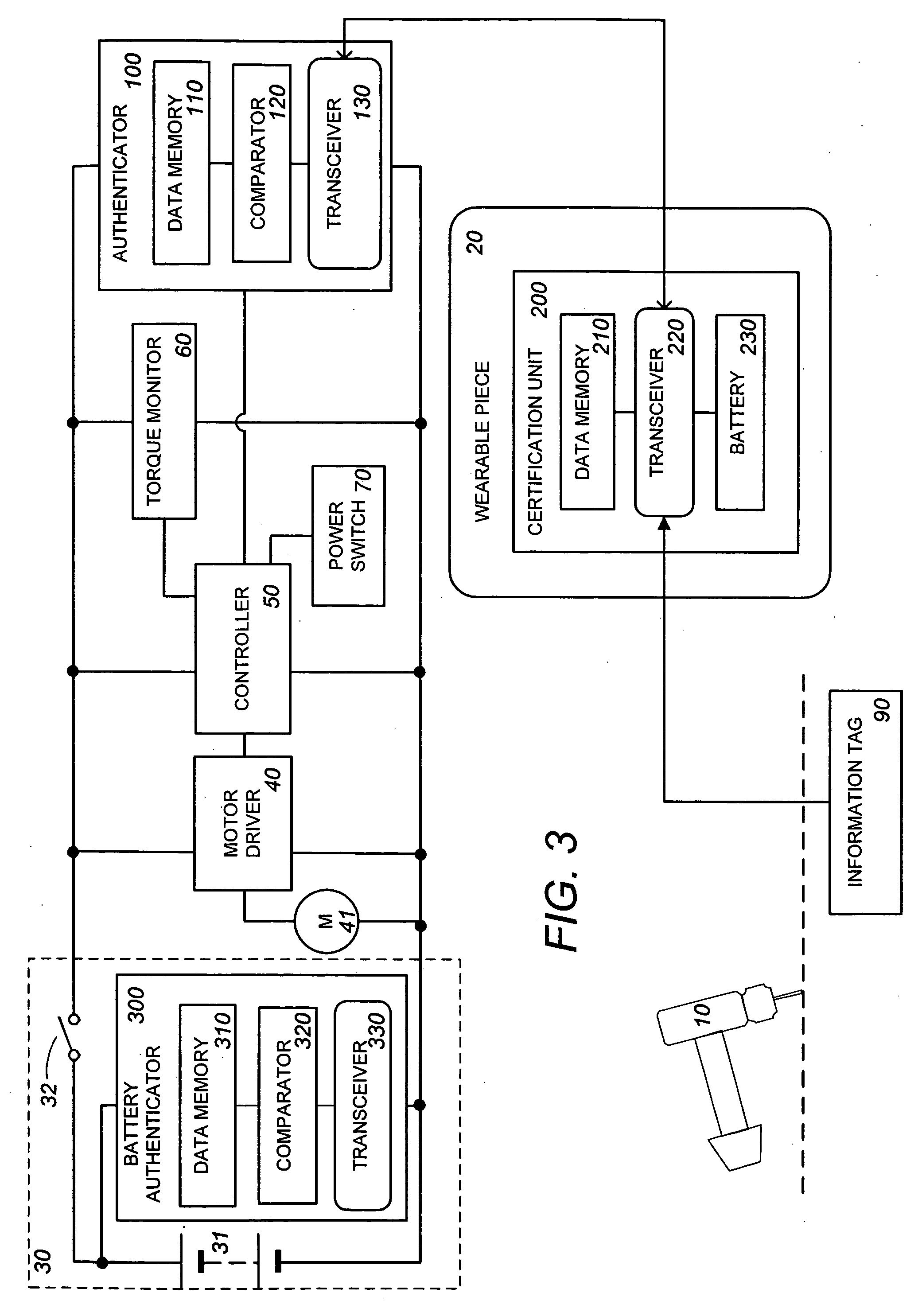
[0017] Referring now to FIGS. 1 and 3, there is shown a power tool system in accordance with a preferred embodiment of the present invention. The system includes a power tool 10 and a wearable piece 20 configured to be worn on a user. The power tool is a hand-held tool, for example, such as a battery operated power screwdriver, drill, or wrench, and has a casing 12 accommodating a motor, a battery pack 30 detachable to the casing, a chuck 14 holding a tool bit, and a grip 16 shaped to be grasped by the user's hand. The wearable piece 20 is prepared in the form of a wrist watch, a band or a card adapted to fit on a wrist or any other part of the user's body or to be carried in a clothing pocket for communication with the power tool 10.

[0018] As shown in FIG. 3, the power tool 10 has a circuit configuration composed of a motor driver 40 for a reversible motor 41, a controller 50 controlling the motor driver 40 for varying the speed or torque of the motor, a torque monitor 60 for obta...


PUM


Abstract

A power tool system with enhanced antitheft capability has a hand-held power tool and a wearable piece worn by the user. The wearable piece incorporates a certification unit which stores an identification code specifying the power tool and transmits the identification code to an authenticator incorporated in the power tool. The authenticator reads the identification code from the certification unit and to provide an authentication signal when the identification code is authenticated to be eligible for a privileged use of the power tool. The power tool is enabled only in response to the authentication signal, and otherwise disabled for avoiding unauthorized use. A communication is established between the certification unit and the authenticator for transmission of the identification code, while the user holds the power tool with the wearable piece carried on.

Description

TECHNICAL FIELD [0001] The present invention is directed to a power tool system, and more particular to an antitheft power tool system which permits the use of a power tool only by an authenticated user. BACKGROUND ART [0002] Japanese Patent Publication No. 2002-18744 A discloses a power tool management system which is designed to generate maintenance information prompting a user to make a suitable maintenance when a cumulative use of the power tool satisfies a predetermined criterion. The system includes a management unit which is provided as a separate entity from the power tool and is configured to give the criterion to the power tool by means of a radio transmission. The management unit is also configured to set one of predetermined operation modes, one being a normal mode which permits the power tool to operate upon actuation of a power switch, and the other being a disable mode which inhibits the power tool from operating even upon actuation of the power switch. In this sense,...

Claims


Application Information

Patent Timeline
Patent Type & Authority Applications(United States)
IPC IPC(8): H04L9/32
CPCB25F5/00
Inventor INNAMI, TERUHISAIKEDA, MASAKITANAKA, NAOTAKEKUBOTA, ATSUMASAMIWA, TATSUYA
Owner MATSUSHITA ELECTRIC WORKS LTD
Why Eureka
Try Eureka