
Assembly containing stacks of a web of material

Inactive Publication Date: 2006-08-17
RESTATIC PRODS
View PDF1 Cites 1 Cited by
  • Summary
  • Abstract
  • Description
  • Claims
  • Application Information

AI Technical Summary

Benefits of technology

[0017] The above mentioned inconvenience concerning “face change” when changing between stacks of the two packs can be eliminated in at least two ways, which are included in the invention. According to one of these ways, the strip material is twisted half a turn, in other words 180°, about its longitudinal axis in each connection between the stacks of the two packs, alternately in one and the other direction.
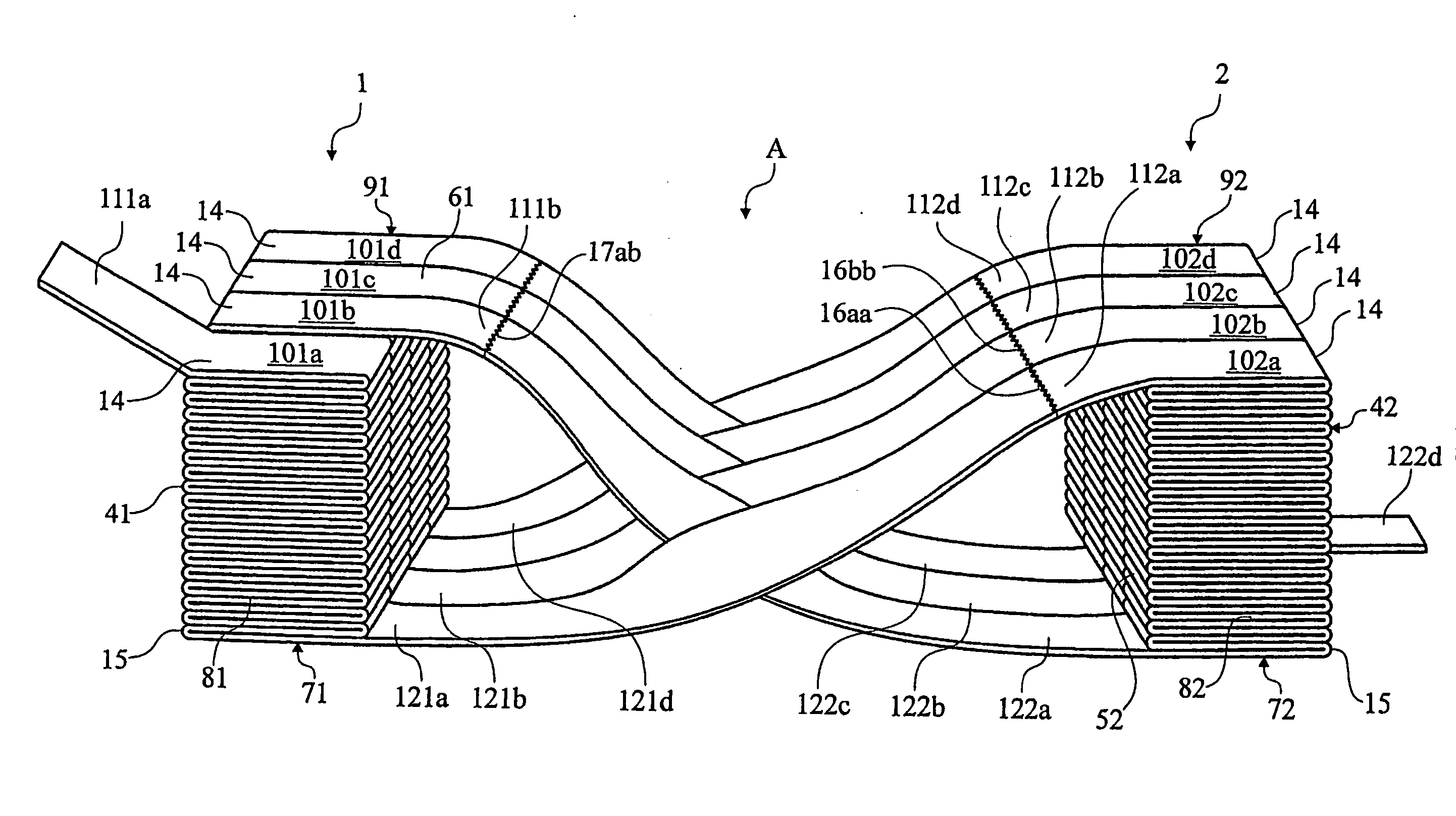
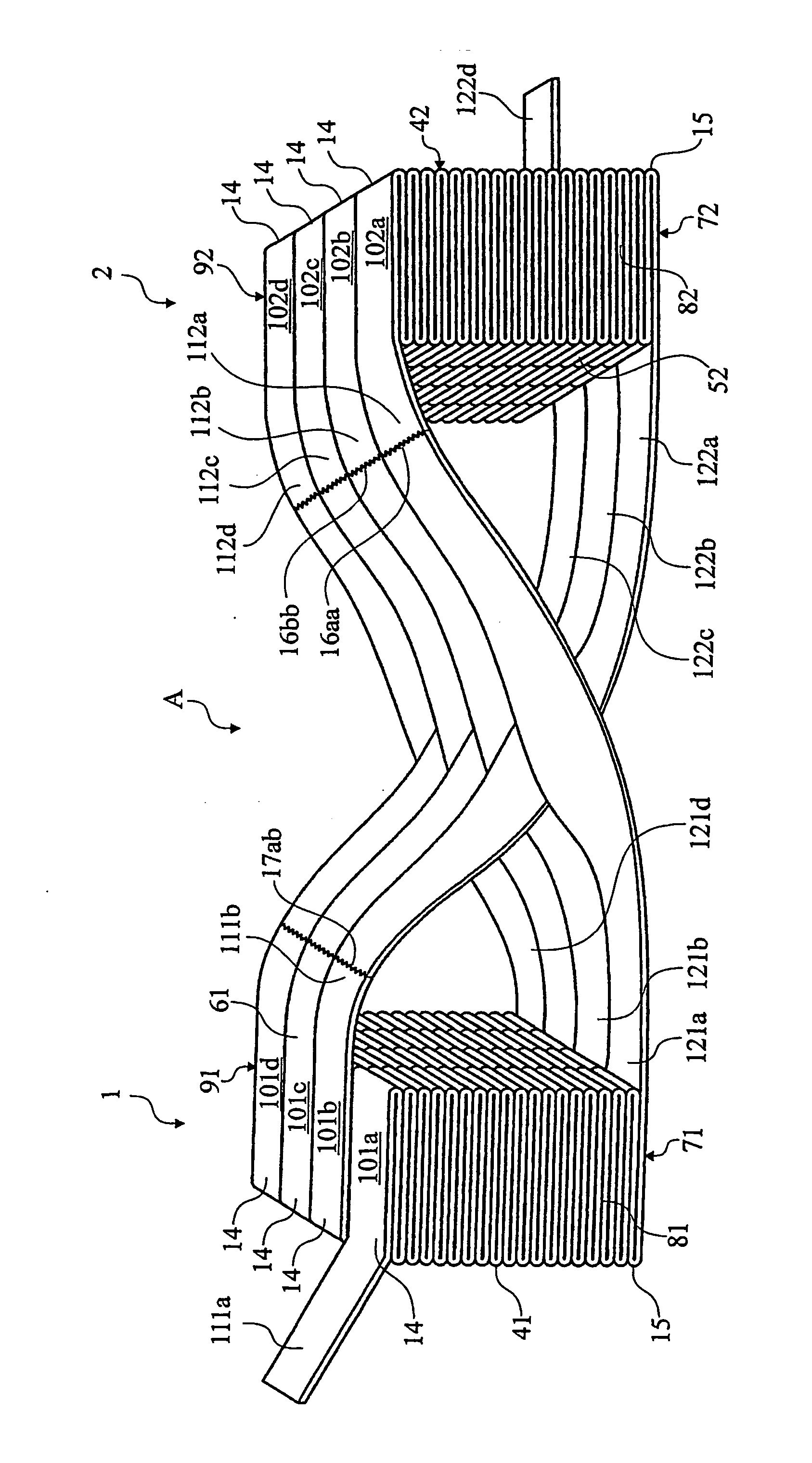
[0018] According to an other way, which is a feature of the most preferred embodiment of the invention, the said inconvenience is eliminated therein that one of the packs is turned 180° about an axis extending between two opposite sides of the pack, so that the first or the second sides of the packs, preferably the second sides, face one another, when the sides facing one another are parallel and said fifth and said sixth sides, respectively, of the two packs are turned in the same direction. According to this embodiment, the connections between the stacks of the packs are not twisted about their longitudinal axis, which facilitates the preparation of the assembly substantially.
[0021] At the same time as the strip-shaped material is fed out, e.g. in a feeding unit of a machine for some kind of conversion of the strip material, by pulling the material, starting in the said leading end of the assembly, a new assembly may be installed in the feeding unit, and the trailing end of material of the assembly which is being fed out may be joined to the leading end of the new assembly. In this way a completely continuous feeding is made possible, i.e. without interruptions because of change of assembly.
[0023] One may also conceive that a plurality of assemblies of the above mentioned kind are joined to one another in advance, i.e. so that the trailing end of a first assembly is joined to the leading end of a second assembly, the trailing end of which is joined to the leading end of another possible assembly, and so on, so that a chain of interconnected assemblies is established. These interconnected assemblies are suitably provided in a common casing, cassette or the like, or are packed together by means of tape, strings or corresponding to form a multi-assembly, which can be transported, handled and entered into the feeding unit of the machine or other device where the strip-shaped material shall be unfolded. It is understood that a multi-assembly of that type, which has a leading end and a trailing end, can rationalise the handling still further.

Problems solved by technology

In the opposite case, e.g. if one can say that the strip material has a top surface and a different bottom surface, it is, on the other hand, an inconvenience.

Method used


Image

  • Assembly containing stacks of a web of material
  • Assembly containing stacks of a web of material

Examples


Embodiment Construction

[0026] A prototype embodiment of an assembly A according to the invention is shown in the drawing. It consists of two essentially parallelepipedic units, in this text referred to as a first pack 1 and second pack 2, the shape and size of which may be adapted to international standards for transportation. Each pack consists of a plurality (more than two; equally many in each pack) of parallel stacks abutting one another, of strip-shaped material, which is folded in a fanfold manner between the ends of the stacks. With reference to the direction of feeding the strip material from the packs, the first folds in the stacks are designated 14, while the last folds are designated 15.

[0027] The first stack of the first pack 1 is designated 101a, the second stack is designated 101b, etc. In the illustrated case, the case contains four stacks. The last stack of the first stack is designated 101d. In the second pack 2, the stacks are correspondingly designated 102a, 102b, 102c and 102d in orde...


PUM

PropertyMeasurementUnit
Timeaaaaaaaaaa
Angleaaaaaaaaaa

Abstract

The invention concerns an assembly (A) containing a plurality of stacks of strip shaped material, which is fanfolded in the stacks between a leading end (111a, 112a) in a first end of the stacks and a trailing end (121a, 122a) in a second end of the stacks, and arranged to be able to be fed out through unfolding of the material continuously at least until the assembly has been emptied. The assembly contains two such packs (1, 2) each of which contains a plurality of such stacks (101a-d, 102a-d) arranged side by side. The leading ends and the trailing ends of the strip material of the stacks of the two packs are alternately joined to one another, so that a continuous strip is achieved with a leading end (111a) of the assembly in a first stack of one of the packs and a trailing end (122d) in a last stack of the other pack. The joined strip material sections between the trailing ends of the stacks of the second pack and the leading ends of the stacks of the first pack extend between the joined strip material sections between the trailing ends of the stacks of the first pack and the leading ends of the second pack. A plurality of such assemblies (A) may be spliced to form a multi-assembly.

Description

TECNICAL FIELD [0001] The invention concerns an assembly containing a plurality of stacks of a web of material which is fanfolded in the stacks between a leading end in a first end of the stacks and a trailing end in a second end of the stacks, and arranged to be able to be fed out by continuously unfolding the web of material at least until the assembly has been emptied. The invention also concerns the preparation of the assembly and a method for feeding out a web of material, including use of the assembly of the invention. BACKGROUND OF THE INVENTION [0002] The invention has been developed with the primary objective to provide spliced strips intended to be included in a system for automatic manufacturing of disposable sanitary towels, napkins, and the like. In such products, layers of non-woven materials are included, which form a surface layer on the top side of the product The starting material is strips of non-woven material, which are difficult to splice between one roll of ma...

Claims


Application Information

Patent Timeline
IPC IPC(8): D01G25/00B65H45/101
CPCB65H45/1015B65H2701/18242B65H2701/11231B65H2301/42162
Inventor ANDREASSON, BENGT
Owner RESTATIC PRODS
Learn More