
A split-type tool setting instrument installation and adjustment device and its positioning method

A technology of adjusting device and tool setting instrument, which is applied in the direction of feeding device, automatic control device, manufacturing tools, etc., can solve the problems of dimensional accuracy fluctuation, high labor cost, workpiece scrapping, etc., and achieve error reduction, accurate position, and elimination of tool parameters the effect of the change

Active Publication Date: 2019-11-22
KEDE NUMERICAL CONTROL CO LTD
View PDF7 Cites 0 Cited by
  • Summary
  • Abstract
  • Description
  • Claims
  • Application Information

AI Technical Summary

Problems solved by technology

[0002] With the development of manufacturing technology and industrial automatic control technology, higher requirements are put forward for the degree of automation and intelligence of the manufacturing industry. When the tool is worn, broken or damaged, it is difficult for the operator to detect and correct it in time, especially the diameter Smaller drill bit tools will cause more loss of subsequent tools or even scrapping of workpieces; when the machine tool is in production and processing, as the ambient temperature changes and the workload changes, the thermal deformation of the machine tool occurs at any time and drives the tool As a result, the dimensional accuracy of the products processed by the same machine tool in the workshop at different times in the morning / middle / night fluctuates greatly
The traditional measurement method is inefficient; the delivery cycle is long; the machine takes up a lot of non-processing time; the labor cost is high; the processing accuracy depends on the quality of the operator and is unstable

Method used


Image

  • A split-type tool setting instrument installation and adjustment device and its positioning method
  • A split-type tool setting instrument installation and adjustment device and its positioning method
  • A split-type tool setting instrument installation and adjustment device and its positioning method

Examples


Embodiment 1

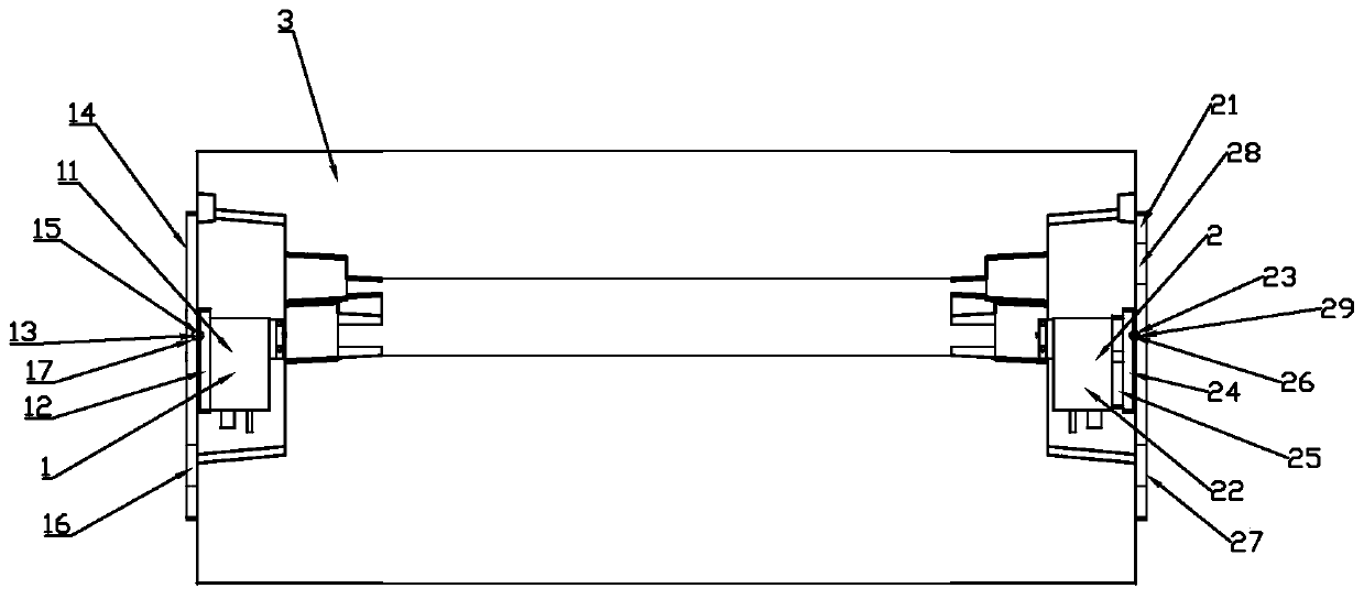
[0037] Such as Figures 1 to 3 As shown, a split-type tool setting instrument installation and adjustment device includes a tool setting instrument transmitting unit 1 and a tool setting instrument receiving unit 2;

[0038] The launching unit 1 of the knife setting instrument includes a launching end 11 of the knife setting instrument, a launching end adjusting plate 12, a steel ball 13 at the launching end and a supporting plate 14 at the launching end, and the launching end 11 of the knife setting instrument is connected to the launching end adjusting plate 12, the launch end steel ball 13 is placed in the connection hole I15 outside the launch end adjustment plate 12, and the launch end support plate 14 is connected to the outside of the launch end adjustment plate 12;

[0039] The tool setting instrument receiving unit 2 includes a receiving end support plate 21, a tool setting instrument receiving end 22, a receiving end steel ball 23, a receiving end adjustment plate 24...

Embodiment 2

[0049] Such as figure 1 , figure 2 with Figure 4 As shown, a split-type tool setting instrument installation and positioning method for adjusting the device, the split-type tool setting instrument installation and adjustment device, the positioning method includes the following steps:

[0050] S1: Fix the launcher 11 of the tool setting instrument to the inner side of the launcher adjustment plate 12 by screws;

[0051] S2: Place the launch end steel ball 13 in the connection hole I15 on the outside of the launch end adjustment plate 12, take the launch end steel ball 13 in the connection hole I15 as a reference, and place the connection hole on the inside of the launch end support plate 14 III17 is engaged on the outer side of the launching end steel ball 13, and the launching end supporting plate 14 is connected to the outer side of the launching end adjusting plate 12 with screws, and the launching end steel ball 13 is arranged in the connection hole I15 and the In the...

Embodiment 3

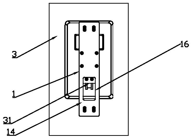
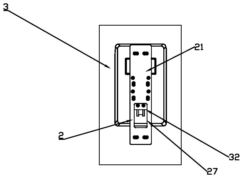
[0063] Such as Figure 4 As shown, the difference between this embodiment and Embodiment 1 is that a vertical waist-shaped groove I16 is arranged on the support plate 14 of the transmitting end, and a horizontal waist-shaped groove 28 is arranged on the upper end of the support plate 21 of the receiving end. The lower end of the end support plate 21 is provided with a vertical waist-shaped groove II 27 .

[0064] Preferably, the transmitting end 11 of the tool setting instrument is a T55AD1030-BD-650 laser transmitter, and the receiving end 22 of the tool setting instrument is an IS0103 laser receiver.

[0065] Preferably, the connecting piece I31 passes through the vertical waist-shaped groove I16 on the launch end support plate 14 to connect the launch end support plate 14 to one side of the machine bed 3;

[0066] The connecting piece II32 connects the receiving end support plate 21 to the other side of the machine bed 3 through the vertical waist-shaped groove II27 on the...


PUM


Abstract

The invention discloses a split type tool checking instrument mounting and regulating device. The split type tool checking instrument mounting and regulating device comprises a tool checking instrument emitting unit and a tool checking instrument receiving unit, wherein the tool checking instrument emitting unit comprises a tool checking instrument emitting end, an emitting end regulating plate, an emitting end steel ball and an emitting end supporting plate; the tool checking instrument receiving unit comprises a receiving end supporting plate, a tool checking instrument receiving end, a receiving end steel ball, a receiving end regulating plate and a transition plate; and the tool checking instrument emitting end is opposite to the tool checking instrument receiving end. According to the split type checking instrument mounting and regulating device and the positioning method thereof disclosed by the invention, a tool can be positioned at any time, so that changes, caused by thermal deformation of a machine tool, of the tool are greatly eliminated, and therefore, potential risk caused by manual tool checking and parameter input are completely avoided.

Description

technical field [0001] The invention belongs to the technical field of manufacturing and industrial automatic control equipment, and in particular relates to a split-type tool setting instrument installation and adjustment device and a positioning method thereof. Background technique [0002] With the development of manufacturing technology and industrial automatic control technology, higher requirements are put forward for the degree of automation and intelligence of the manufacturing industry. When the tool is worn, broken or damaged, it is difficult for the operator to detect and correct it in time, especially the diameter Smaller drill bit tools will cause more loss of subsequent tools or even scrapping of workpieces; when the machine tool is in production and processing, as the ambient temperature changes and the workload changes, the thermal deformation of the machine tool occurs at any time and drives the tool As a result, the dimensional accuracy of the products proc...

Claims


Application Information

Patent Timeline
Patent Type & Authority Patents(China)
IPC IPC(8): B23Q15/28B23Q15/18B23Q17/24
CPCB23Q15/18B23Q15/28B23Q17/2419
Inventor 陈虎郝天阳李文庆李俊张继德李荣东
Owner KEDE NUMERICAL CONTROL CO LTD
Learn More