Two-piece tube

Inactive Publication Date: 2006-08-17
BOSCH REXROTH MECHATRONICS
View PDF15 Cites 1 Cited by
  • Summary
  • Abstract
  • Description
  • Claims
  • Application Information

AI Technical Summary

Benefits of technology

[0009] Preferably, on the inside circumference of the tube, clearances are provided, which define-runup faces for the roller bodies, and the clearances are located in the region of the contact face of the tube halves. In a tube of the invention, it can happen that a step is created in the region of the contact faces, caused by a minimal displacement of the tube halves relative to one another. These steps woul

Problems solved by technology

A transverse displacement, however, is made

Method used


Image

  • Two-piece tube
  • Two-piece tube
  • Two-piece tube

Examples


Example

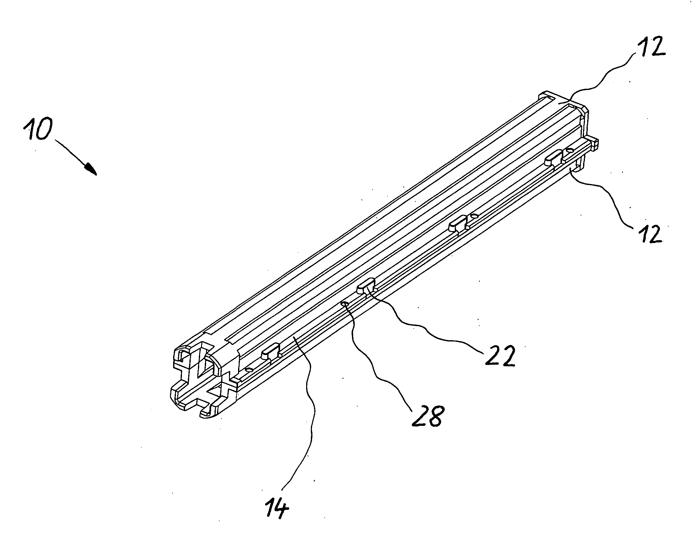
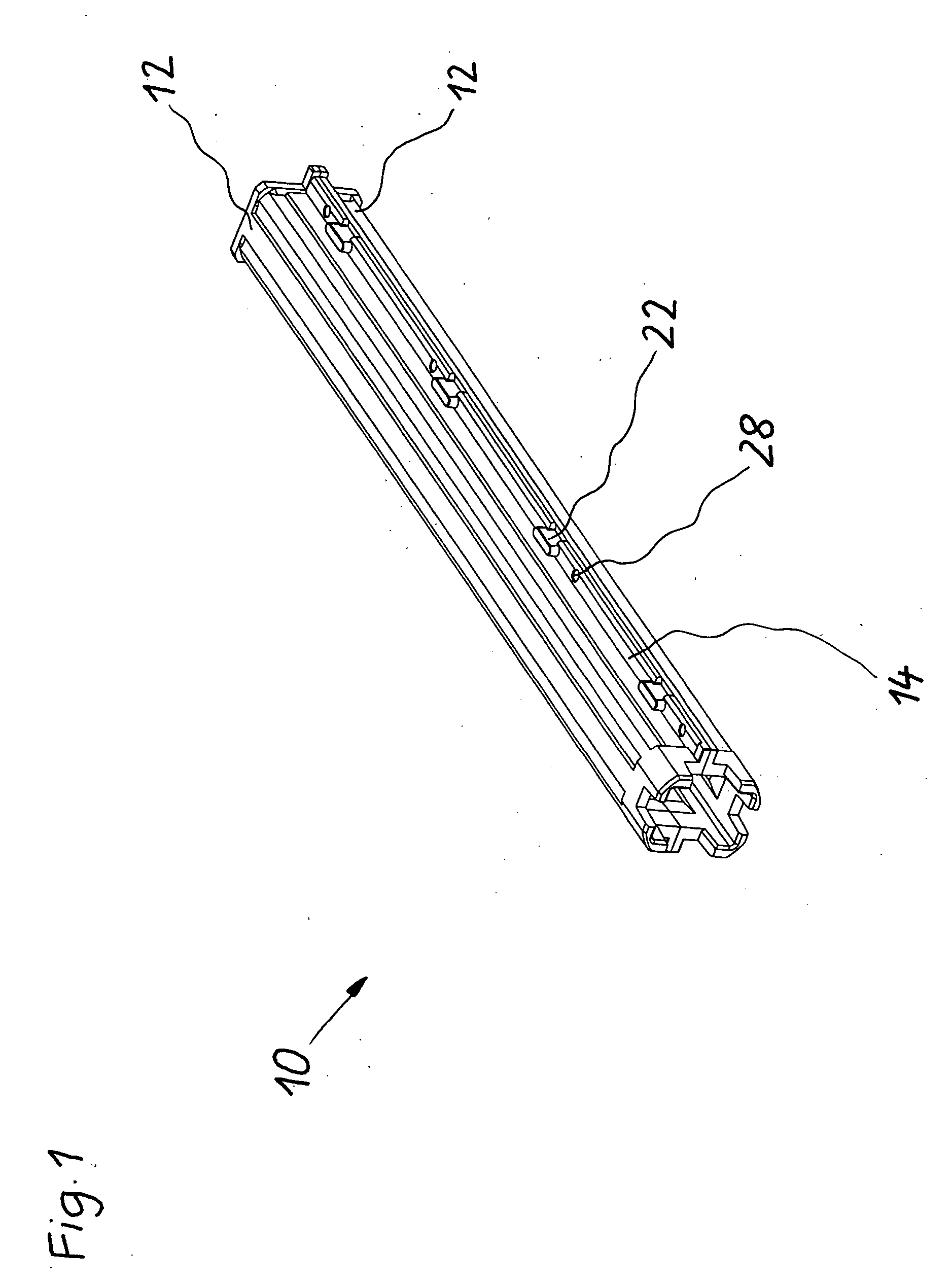
[0013] In FIG. 1, a tube of the invention is identified very generally by reference numeral 10. It comprises two identical tube halves 12, which are joined together, rotated 180° relative to one another. This tube is intended to receive roller-like roller bodies, not shown, and it therefore has a rectangular internal contour. The tube is used as a return tube in a linear roller bearing, namely a roller rail guide. The two tube halves 12 are made from plastic by injection molding.

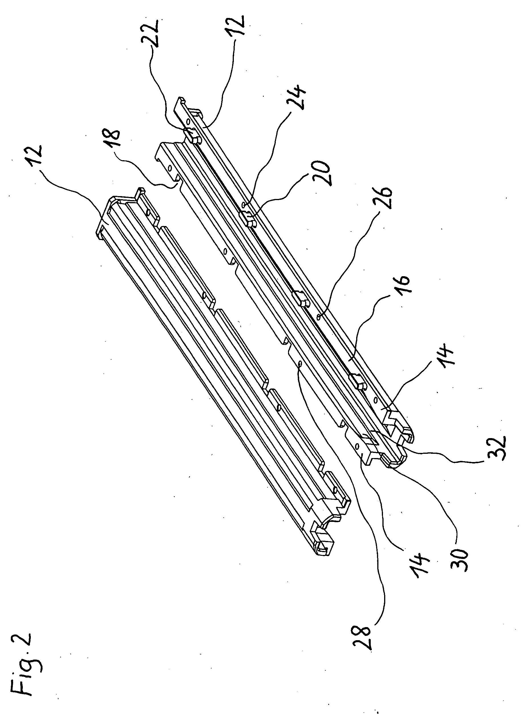
[0014] In FIG. 2, the two tube halves 12 are shown in more detail. The tube halves 12 have two flange portions 14, on which flat contact faces 16 are provided. The flat contact faces 16 are located in the same plane that contains the straight center line of the tube.

[0015] A plurality of recesses 18, open toward the side, are provided on one flange portion 14. On the other, complementary flange portion 14, engagement portions 20 are provided. They are formed as T-shaped extensions 22, which are capable of ...


PUM

PropertyMeasurementUnit
Circumferenceaaaaaaaaaa
Displacementaaaaaaaaaa

Abstract

A tube for receiving roller bodies has two tube halves that are joined together in form-locking fashion so as to provide a form lock, and the form lock is configured so that it is undoable only whenever there are no roller bodies located in the tube.

Description

BACKGROUND OF THE INVENTION [0001] The invention relates to a tube for receiving roller bodies, comprising two tube halves, which are joined together in form-locking fashion. [0002] Such tubes are used for instance in linear roller bearings and ball-and-screw spindle drives for restoring the roller bodies, as is known from German Patent Disclosure DE 102 27 689 A1. In this reference, a tube 11 is shown, comprising two identical tube halves 15. For form-locking connection of the tube halves, protrusions 16 and complementary recesses 17 are provided. Snap connections are also provided, comprising projections 19 and grooves 20. The protrusions and recesses serve primarily to align the two tube halves relative to one another, while the snap connections prevent the tube from falling apart. [0003] Snap connections have the disadvantage that they must be manufactured relatively precisely, if a play-free connection of the two tube halves is to be assured. This problem is exacerbated by the ...

Claims


Application Information

Patent Timeline
IPC IPC(8): B23K20/00
CPCF16C29/06F16C29/0611F16L9/22
Inventor MUEHLECK, MARTINDORN, STEFAN
Owner BOSCH REXROTH MECHATRONICS
Why Eureka
Try Eureka