Automatic shift knob actuator

Inactive Publication Date: 2005-03-24
KEY SAFETY SYST
View PDF6 Cites 11 Cited by
  • Summary
  • Abstract
  • Description
  • Claims
  • Application Information

AI Technical Summary

Benefits of technology

[0006] The present invention comprises a stick shift handle and an actuator for releasing the stick shift handle for movement between various gear positions. The actuator has a housing that is disposed within the stick shift handle. In contrast to existing stick shift handle assemblies, however, the inventive stick shif

Problems solved by technology

Problems may arise with the actuator that unlocks the stick shift handle.
While manufacturers have sought to overcome this problem by placing lubricant between the actuator and the stick shift handle, during frequent use, the lubricant tends to migrate from the area of contact betw

Method used


Image

  • Automatic shift knob actuator
  • Automatic shift knob actuator
  • Automatic shift knob actuator

Examples


Example

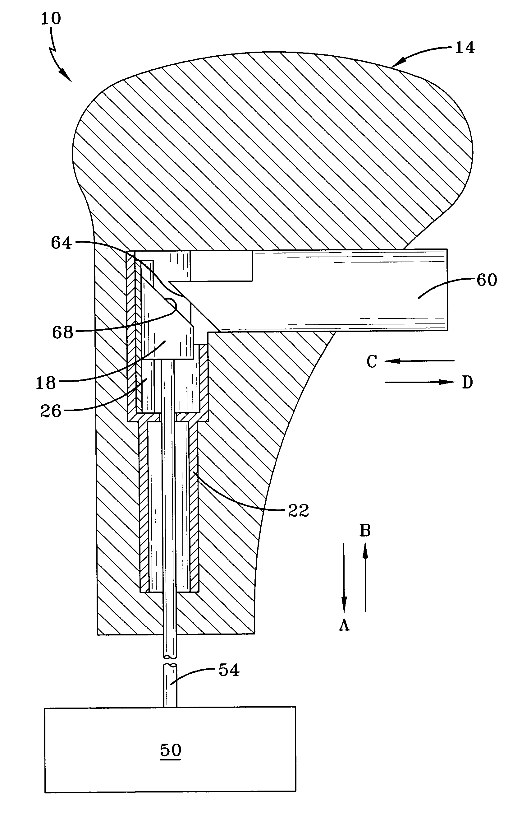
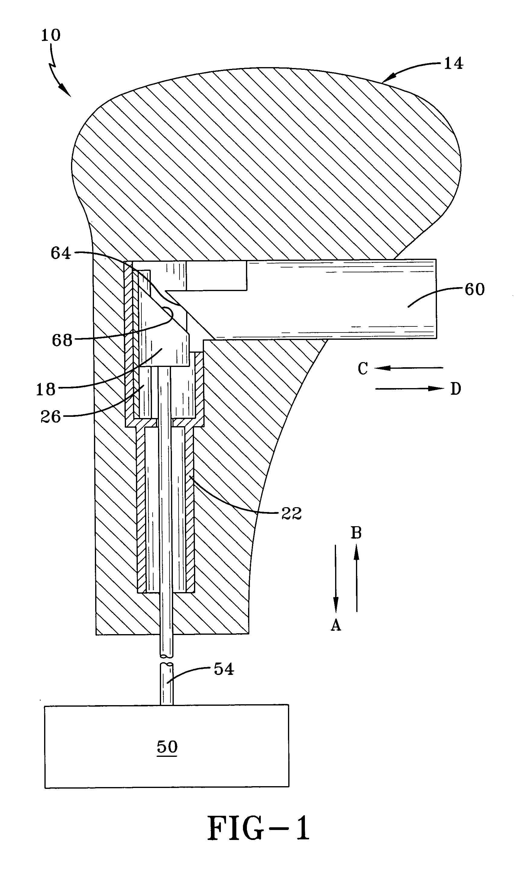
[0019]FIG. 1 illustrates a cross-sectional view of inventive stick shift handle assembly 10. Like existing stick shift handle assemblies, inventive stick shift handle assembly 10 has stick shift handle 14, which allows a driver to shift a vehicle transmission through its various gears. Stick shift handle 14 is prevented from moving from gear shift position to gear shift position by shift lock mechanism 50, here shown schematically.

[0020] To release stick shift handle 14 for movement between the various gear shift positions, a driver presses button 60 in the direction of arrow C. Button 60 has first sloped surface 64, such as a rounded or inclined surface, which also moves in the direction of arrow C to contact second sloped surface 68, here another rounded or inclined surface, of actuator 18. Actuator 18 is housed in housing 22, which may be a separate part or be part of stick shift handle 14. Actuator 18 then moves in the direction of arrow A and transmits its motion to motion tra...


PUM


Abstract

A stick shift handle assembly has a stick shift handle and an actuator for releasing the stick shift handle for movement between a plurality of gear positions. The actuator has a housing. A sleeve is disposed between the actuator and the housing. The sleeve has a first co-efficient of friction lower than a second co-efficient of friction of the housing.

Description

FIELD OF THE INVENTION [0001] This invention relates to an actuator for a stick shift handle assembly. BACKGROUND OF THE INVENTION [0002] A stick shift handle for an automatic transmission permits a driver to change the gears of a vehicle transmission by moving the stick shift handle between various positions. Typically, the stick shift handle is locked in a particular gear position until unlocked by the driver. The driver unlocks the stick shift handle by pressing a release button either at the front of the stick shift handle or on its side, which, in turn, causes an actuator in the stick shift handle to release the stick shift handle from a shift lock mechanism. [0003] Problems may arise with the actuator that unlocks the stick shift handle. Specifically, the stick shift handle, which houses the actuator, is generally made from plastic and fiberglass. This material has a high co-efficient of friction and causes the actuator to experience a fair amount of friction when moved. While...

Claims


Application Information

Patent Timeline
IPC IPC(8): F16H59/02
CPCF16H59/0278F16H61/22Y10S16/30F16H2059/0282Y10T74/20732Y10T74/20612Y10T74/20702Y10T74/2014Y10T74/20085
Inventor JARJOURA, TAMMERSPENCER, BYRON A.CURTIN, EMILYBEATTIE, CALUM
Owner KEY SAFETY SYST
Why Eureka
Try Eureka