Gas heater and combined heat exchanger thereof

A technology of gas water heaters and heat exchangers, which is applied in heat exchange equipment, water heaters, fluid heaters, etc., and can solve problems such as limited effects and inability to effectively improve the thermal efficiency of water heaters

Inactive Publication Date: 2016-04-13
TAIWAN SAKURA
View PDF7 Cites 1 Cited by
  • Summary
  • Abstract
  • Description
  • Claims
  • Application Information

AI Technical Summary

Problems solved by technology

[0005] Although there are fins that use the design of the formed convex part to prolong the residence time and distance between the gas combustion heat and the fins, so as to improve the heat absorption effect of the fins, the effect is still quite limited and cannot effectively improve the thermal efficiency of the water heater
The heat efficiency of above-mentioned water heater also can only reach 80.9%, and its effect is still limited

Method used


Image

  • Gas heater and combined heat exchanger thereof
  • Gas heater and combined heat exchanger thereof
  • Gas heater and combined heat exchanger thereof

Examples


no. 1 example

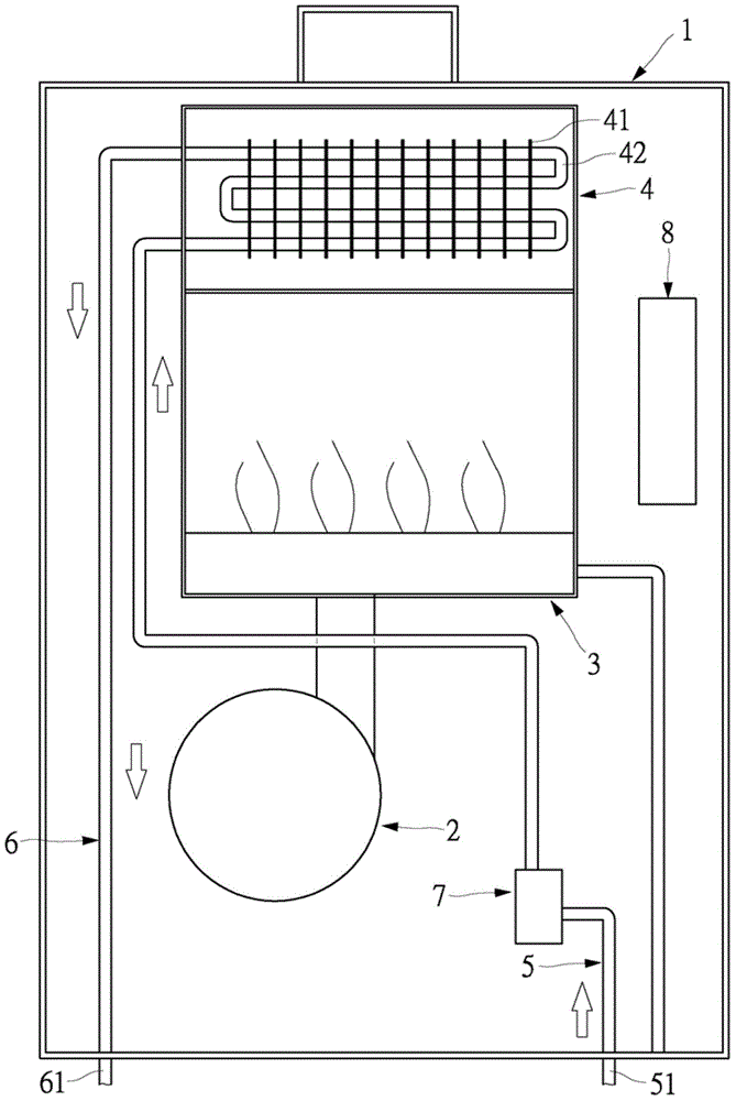
[0080] See figure 1 , The present invention provides a gas water heater, which includes a body 1, a fan 2, a combustor (fire exhaust) 3 and a heat exchanger 4. The body 1 is a hollow shell. The fan 2, the burner 3 and the heat exchanger 4 are arranged inside the body 1. The positions of the fan 2, the burner 3 and the heat exchanger 4 are not limited, and can be added as needed Variety. In this embodiment, the fan 2, the combustor 3 and the heat exchanger 4 are sequentially arranged inside the body 1 from bottom to top, and the combustor 3 is located between the fan 2 and the heat exchanger 4. When the burner 3 is ignited, the burner 3 can produce high-temperature combustion gas. The combustion gas is pushed upwards, and the combustion gas contacts the heat exchanger 4 for heat exchange operation, so that the water flowing through the heat exchanger 4 can be It is heated from normal temperature to high temperature, and then used as hot water.

[0081] The heat exchanger 4 is co...

no. 2 example

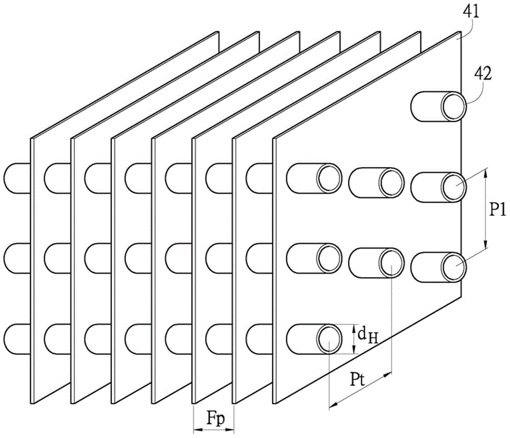
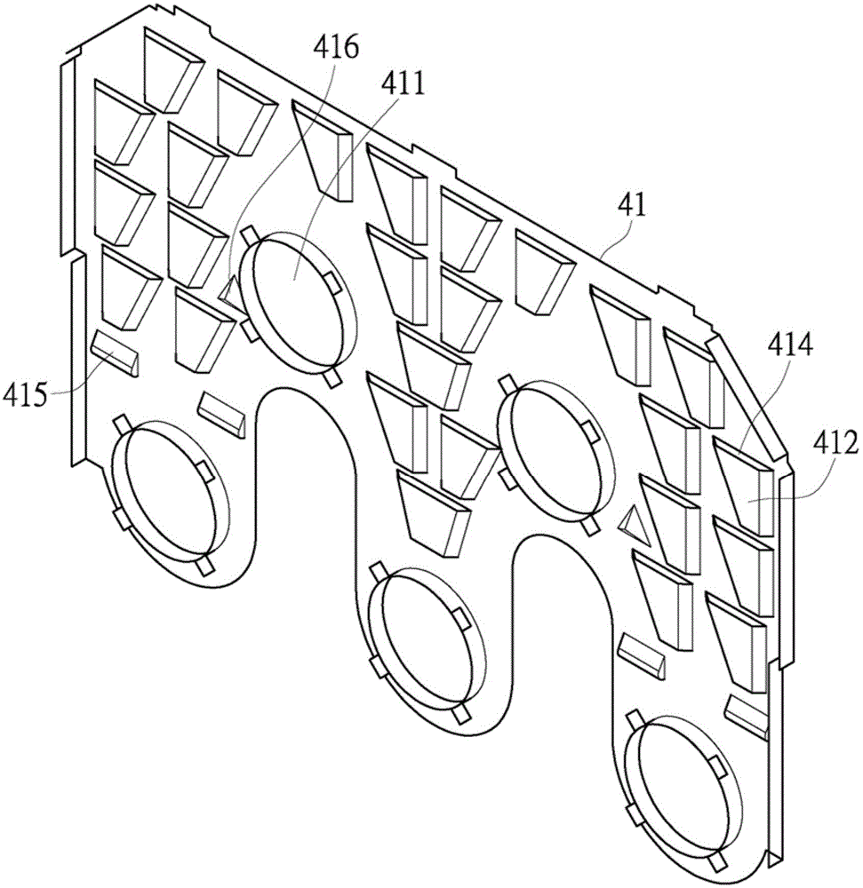
[0105] See Figure 2 to Figure 4 , Figure 8 to Figure 10 This embodiment discloses a pyramid-shaped vortex generator 416. The vortex generators 416 are formed by punching the fins 41 respectively, and the vortex generators 416 can protrude from one side or the other side of the fin 41 respectively. Each vortex generator 416 is a pyramid. The vortex generator 416 has a triangular bottom C and a plurality of inclined surfaces D. The vortex generator 416 is connected to the fin 41 with the bottom C and is defined as follows:

[0106] The distance between every two adjacent fins is Fp, the width of the vortex generator is g1, the length of the vortex generator is gt, the height of the vortex generator is gh, the vertical height distance between the lower edge of the vortex generator and the center point of the water pipe above is Ph, the water pipe The horizontal pitch is Pt, and the longitudinal pitch of the water pipe is Pl.

[0107] If the following relational conditions are met,...


PUM


Abstract

The invention relates to a gas heater and a combined heat exchanger thereof. The combined heat exchanger is designed to be a split-type fin heat exchanger and provided with multiple fins which are arranged at intervals. The fins are provided with protrusions and vortex generators which can be in forms of waves or pyramids. Each wave-shaped vortex generator is defined in that the distance between every two adjacent fins is Fp; the width of each wave-shaped vortex generator is w1, the circular arc radius of an arc of each vortex generator is wr; and the arc angle of an arc of each vortex generator is wa. If conditions for the following relation are satisfied, better heat efficiency can be reached: w1=(1.32-2.86) Fp; wr=(0.4-0/9) Fp; and wa=100-150 degrees.

Description

Technical field [0001] The present invention is to provide a heat exchanger, especially a gas water heater and its compound heat exchanger which can achieve better thermal efficiency. Background technique [0002] According to this, water heaters are currently indispensable devices for general household life. As far as the energy used is concerned, they can be roughly divided into gas water heaters, electric water heaters and solar water heaters, among which gas water heaters are widely used by the general public. [0003] The existing gas water heater is provided with a fan, a burner, and a heat exchanger inside the body. The heat exchanger is connected with a cold water pipe and a hot water pipe. The cold water pipe and the hot water pipe can form a water passage. One end of the cold water pipeline has a cold water inlet, which can be connected to an appropriate water source for inputting cold water to be heated. One end of the hot water pipeline has a hot water outlet, and the ...

Claims


Application Information

Patent Timeline
Patent Type & Authority Applications(China)
IPC IPC(8): F24H1/14F28D1/04F28F1/32
Inventor 吴兢先薛承志杜佩麟陈昭文
Owner TAIWAN SAKURA
Why Eureka
Try Eureka