Method for bonding metallic plates and jig for the bonding of the metallic plates

a technology of metallic plates and jigs, which is applied in the direction of soldering devices, manufacturing tools,auxillary welding devices, etc., can solve the problems of ink flow path distortion and deflection, and achieve the effects of preventing failure of bonding, and simplifying manufacturing processes

Active Publication Date: 2006-08-17
BROTHER KOGYO KK
View PDF7 Cites 11 Cited by
  • Summary
  • Abstract
  • Description
  • Claims
  • Application Information

AI Technical Summary

Benefits of technology

[0010] According to this method, when the pair of jigs sandwich the laminated body of the metallic plates therebetween, the inner cavity of the laminated body communicates with the atmosphere via the atmosphere communication path formed in the at least one of the jigs. Therefore, it is possible to surely release the air from the inner cavity to the outside via the atmosphere communication path before the diffusion bonding is conducted. Accordingly, when the laminated body is heated, the air in the inner cavity is not expanded. As a result, it can be possible to prevent failure of bonding the metallic plates from occurring and non-uniform temperature distribution, which causes distortion of the metallic plate, from occurring. Since the atmosphere communication path is provided in the at least one of the jigs, it is unnecessary to provide a step of providing an atmosphere communication path, which communicates the inner cavity with the atmosphere, on the laminated body side in advance. Accordingly, the manufacturing process can be simplified.
[0011] According to another aspect of the invention, each of a pair of jig

Problems solved by technology

As a result, failure of adhesion may be caused in a portion where a sufficiently large adhesion region is not provided to thereby cause ink to lea

Method used


Image

  • Method for bonding metallic plates and jig for the bonding of the metallic plates
  • Method for bonding metallic plates and jig for the bonding of the metallic plates
  • Method for bonding metallic plates and jig for the bonding of the metallic plates

Examples


Embodiment Construction

[0022] Referring to the accompanying drawings, embodiments of the invention will be explained below.

[0023] This embodiment is an example in which the invention is applied to an inkjet head of an inkjet printer.

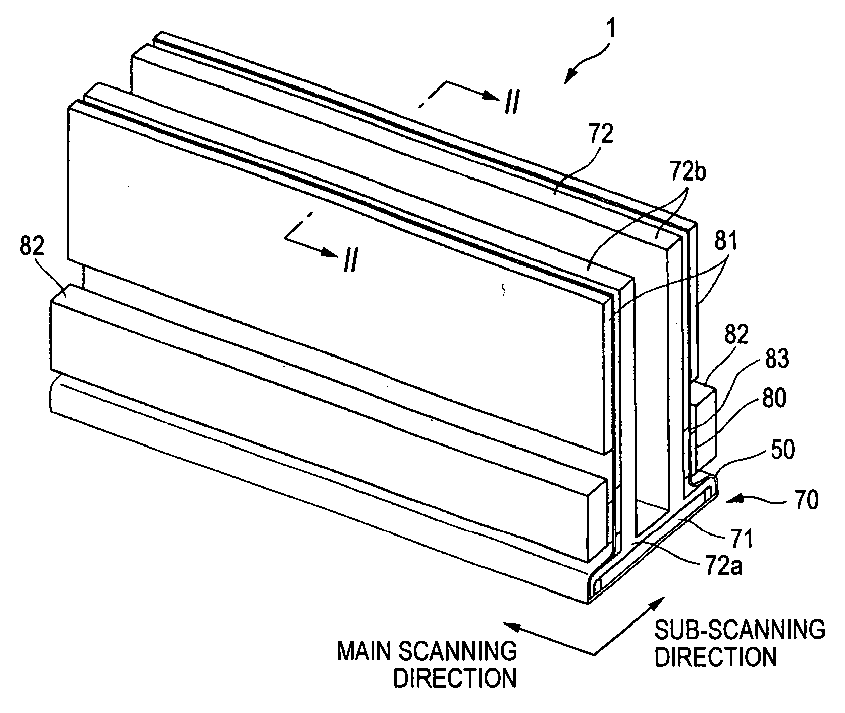
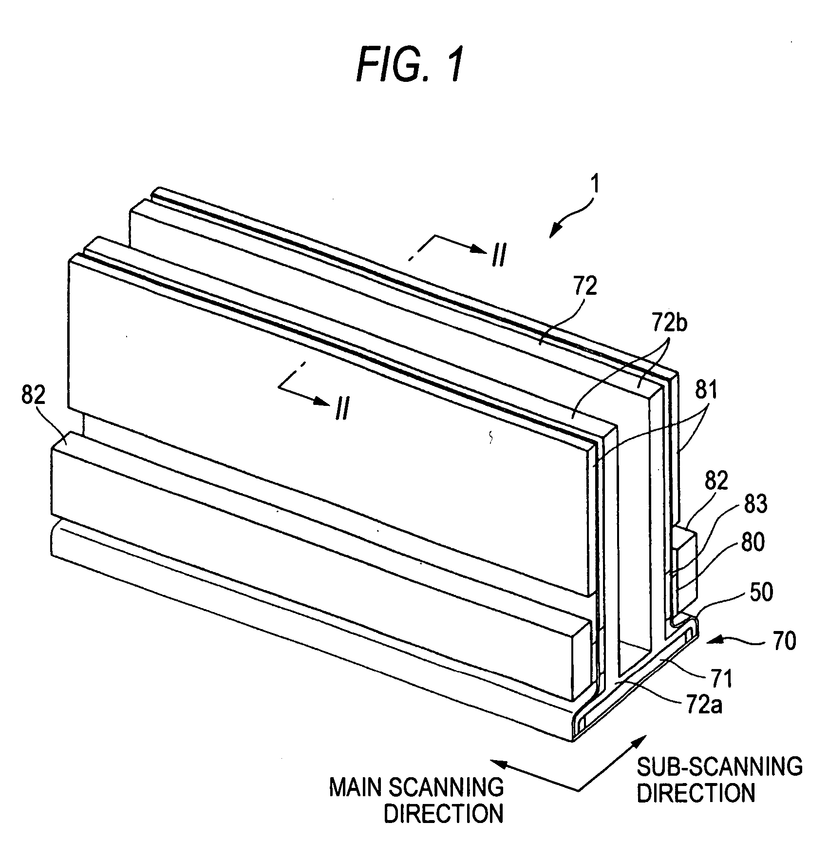
[0024] First of all, referring to FIG. 1, the entire structure of the inkjet head of this embodiment of the invention is explained as follows. FIG. 1 is a perspective view showing appearance of the inkjet head of this embodiment.

[0025] The inkjet head 1 includes a head unit 70 and a base block 71. The head unit 70 has a rectangular shape in plan view and extends in a main scanning direction in terms of ejecting ink to a sheet of paper. The base block 71 is formed with a flow path of ink to be supplied to the head unit 70. A holder supports the base block 71. This holder 72 includes a holding portion 72a and a pair of flat-plate members 72b. The holding portion 72a accommodates the base block 71. The pair of flat-plate members 72b extend from the upper surface of the holding...


PUM

PropertyMeasurementUnit
Pressureaaaaaaaaaa

Abstract

A method for bonding metallic plates includes: sandwiching a laminated body, which includes a plurality of metallic plates and is formed with an inner cavity opening on a surface thereof, between a pair of jigs each having a flat abutment surface abutting against respective surfaces of the laminated body, wherein at least one of the jigs is formed with an atmosphere communication path, which communicates with the inner cavity and atmosphere; and heating the laminated body while applying pressure to the laminated body with the pair of jigs in a lamination direction of the laminated body.

Description

[0001] This application is based upon and claims the benefit of priority from Japanese Patent Application No. 2005-1046 filed on Jan. 6, 2005; the entire contents of which are incorporated herein by reference. BACKGROUND OF THE INVENTION [0002] 1. Field of the Invention [0003] The invention relates to a method for bonding a plurality of laminated metallic plates and a jig for the bonding of the metallic plates. [0004] 2. Description of the Related Art [0005] Hitherto, there has been known as an inkjet head that ejects ink from nozzles, one in which a flow-path unit including an ink flow path therein is formed of a plurality of metallic plates laminated on each other. For example, US 2004 / 0183867 A discloses an inkjet head includes a manifold and a flow-path unit having individual ink flow paths extending from the manifold to the nozzles via pressure chambers. This flow-path unit is formed of a laminated body in which a plurality of metallic plates are laminated and bonded to each ot...

Claims


Application Information

Patent Timeline
IPC IPC(8): B23K31/02B23K37/04
CPCB23K20/021B23K37/0408
Inventor HIROTA, ATSUSHI
Owner BROTHER KOGYO KK
Why Eureka
Try Eureka