Non-invasive scanning device

a scanning device and non-invasive technology, applied in the field of systems, can solve the problems of large size and high cost of scanners used for non-invasive imaging

Inactive Publication Date: 2006-08-17
THE CLEVELAND CLINIC FOUND
View PDF12 Cites 18 Cited by
  • Summary
  • Abstract
  • Description
  • Claims
  • Application Information

AI Technical Summary

Benefits of technology

[0008] In accordance with another aspect of the present invention, an assembly is provided for imaging a small laboratory subject in conjunction with a scanner designed primarily for another application. The assem...

Problems solved by technology

The scanners used for performing noninvas...

Method used


Image

  • Non-invasive scanning device
  • Non-invasive scanning device
  • Non-invasive scanning device

Examples


Embodiment Construction

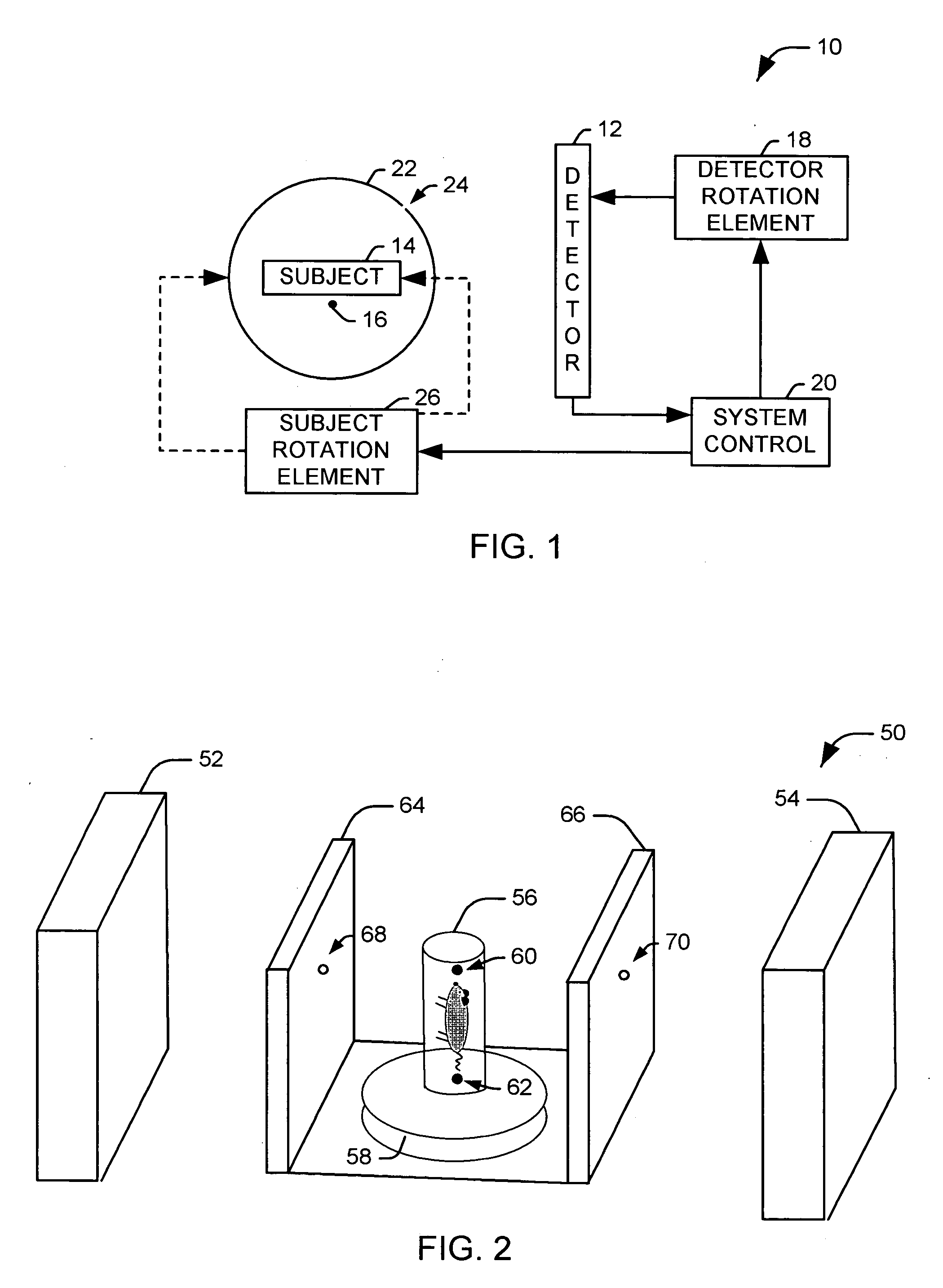
[0016]FIG. 1 illustrates a functional block diagram of scanning assembly 10 in accordance with an aspect of the present invention. The scanning assembly includes at least one detector 12 that is operative to detected radiation emitted from a test subject 14. For example, the at least one detector 12 can include any appropriate detector for detecting radiation from a subject, such as nuclear detectors that detect radiation emitted from the subject, radiological imaging devices (e.g., for computed tomography) that irradiate the subject 14 and detect attenuation of the radiation as it passes through the subject, or a combination of multiple detector types.

[0017] The test subject 14 can have at least one associated calibration marker 16, for example, mounted to a test bed (not shown) associated with the test subject. A given calibration marker is selected to have associated dimensions and radiological properties as to produce a relatively small, easily recognizable point at the detecto...


PUM


Abstract

Methods and systems are provided for radioactive imaging of a test subject. At least one detector is operative to detect a radiation type associated with the subject. A test bed supports the test subject. A collimator assembly is positioned between the test bed and the at least one detector. The collimator assembly is not mechanically coupled to the at least one detector.

Description

RELATED APPLICATION [0001] This application claims priority from U.S. provisional patent application Ser. No. 60 / 652,260, filed on Feb. 11, 2005, the subject matter of which is incorporated herein by reference.FIELD OF THE INVENTION [0002] The present invention relates to a system and method for non-invasive imaging and, in particular, is directed to a system and apparatus for non-invasive imaging of laboratory subjects. BACKGROUND OF THE INVENTION [0003] Modern imaging techniques, such as single photon emission computed tomography (SPECT) allow the imaging of the interior of a target object without physically penetrating the surface of the target. These techniques are used extensively in the medical field. By allowing indirect observation of the interior of the human body, these imaging techniques give medical professionals increased diagnostic information without the accompanying risk of conventional exploratory techniques. [0004] The scanners used for performing noninvasive imagi...

Claims


Application Information

Patent Timeline
IPC IPC(8): H01J35/16G01T1/161
CPCG01T1/1648G01T1/2985
Inventor DIFILIPPO, FRANK P.
Owner THE CLEVELAND CLINIC FOUND
Why Eureka
Try Eureka