
Manipulator-guided gripping device having a deflection safety device that can prevent collisions

Inactive Publication Date: 2006-08-17
KUKA SYSTEMS
View PDF3 Cites 25 Cited by
  • Summary
  • Abstract
  • Description
  • Claims
  • Application Information

AI Technical Summary

Benefits of technology

[0004] An object of the present invention is to provide a gripping device that exhibits better behavior in case of crashes and collisions.
[0005] According to the invention, a 
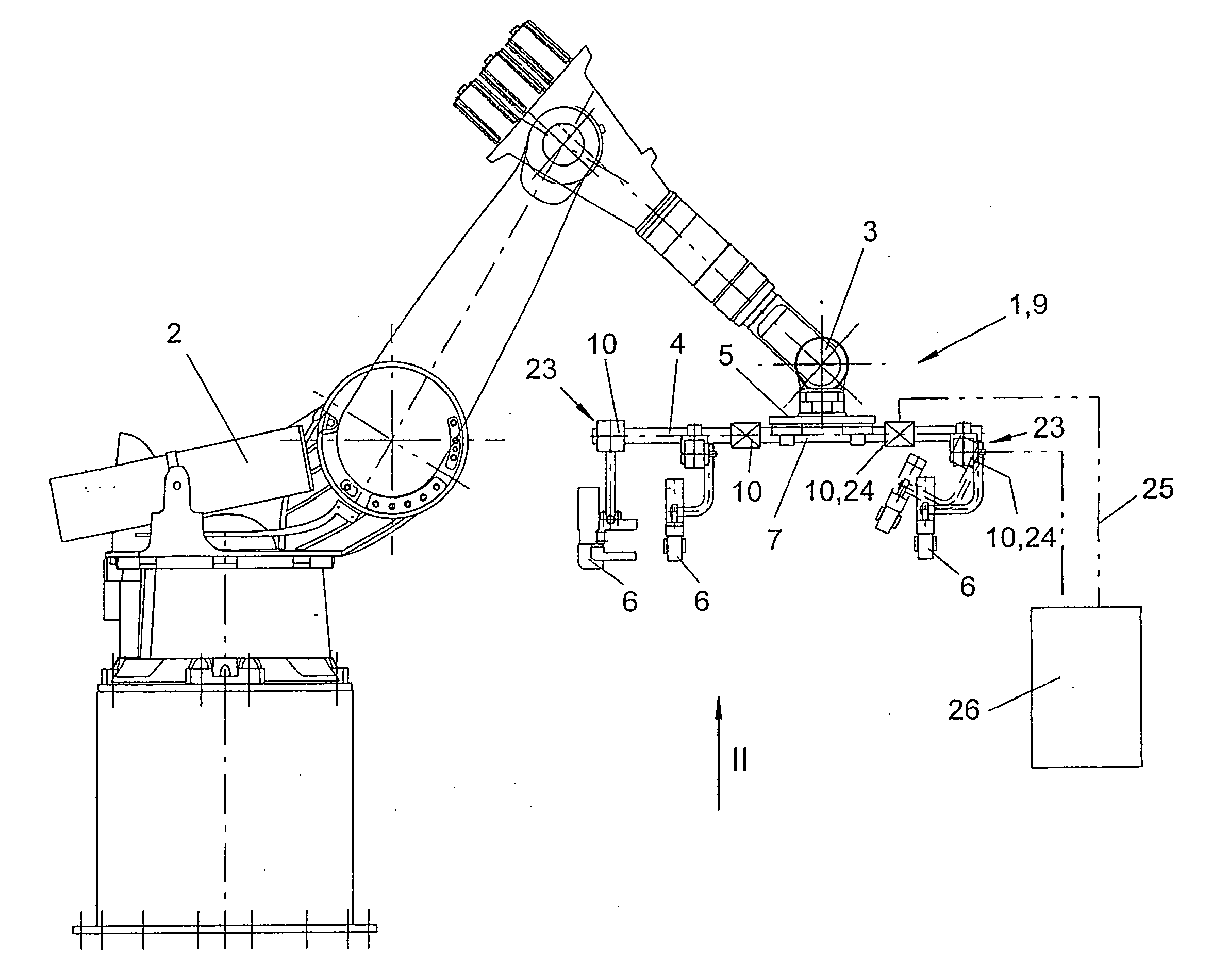
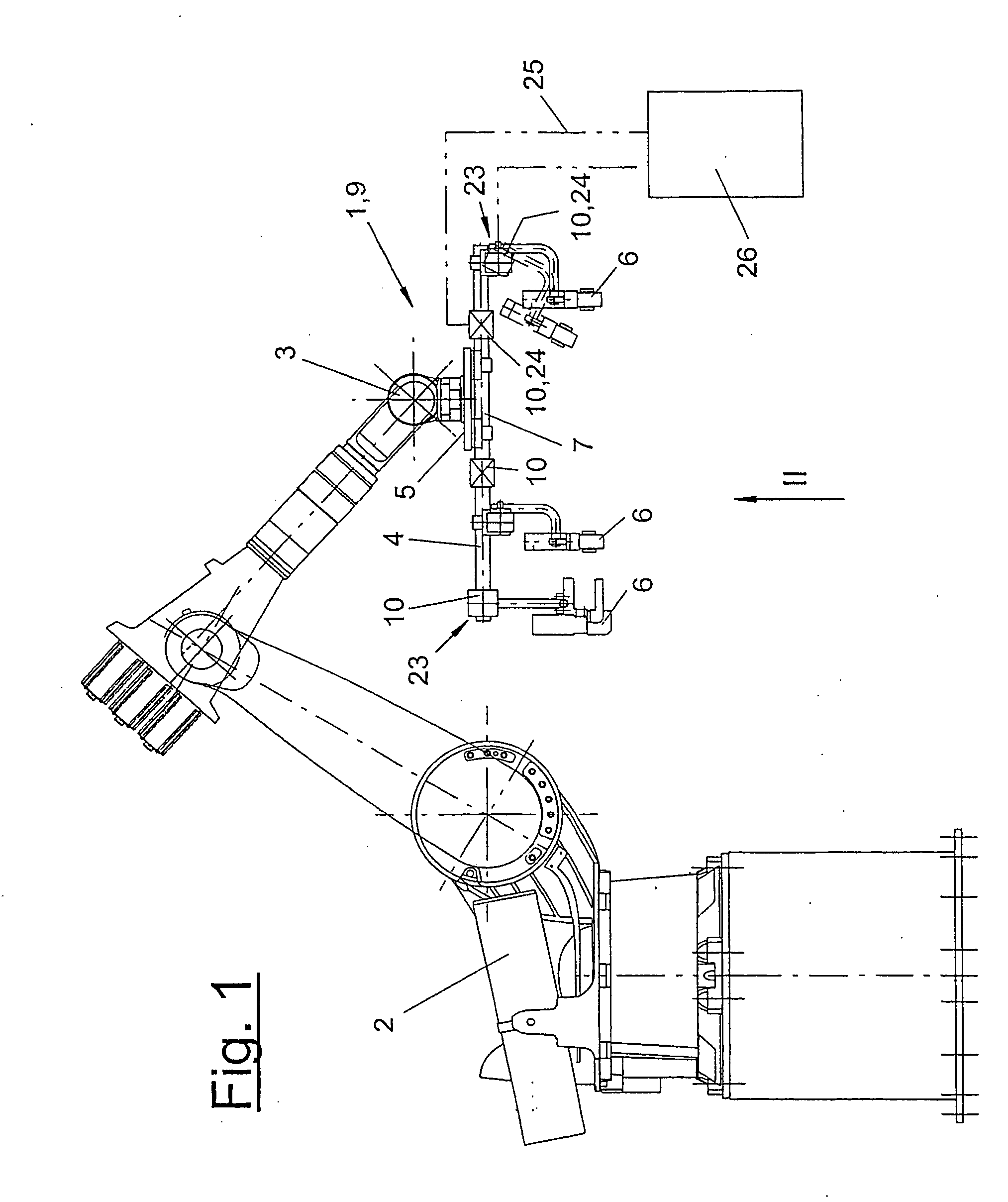
manipulator-guided gripping device is provided for workpieces such as body parts in a body shell. The gripping device has a plurality of device parts and a safety means for detecting changes in geometry with at least one deflectable safety device at the device parts. The deflectable safety device is provided at the various components or parts of the gripping device. The safety device is preferably present as multiple devices to provide the advantage that it makes possible the deflection of the colliding parts of the gripping device in case of a crash or collision, as a result of which plastic deformations and other damage are avoided on the gripping device. Due to the deflected position, it is, moreover, optically signaled to an operator that a collision has taken place. In addition, suitable detectors or sensors may be present at the deflectable safety device, which detect a deflecting movement and report it in a suitable manner, for example, signal it to a process control, automatically trigger an alarm or the like.
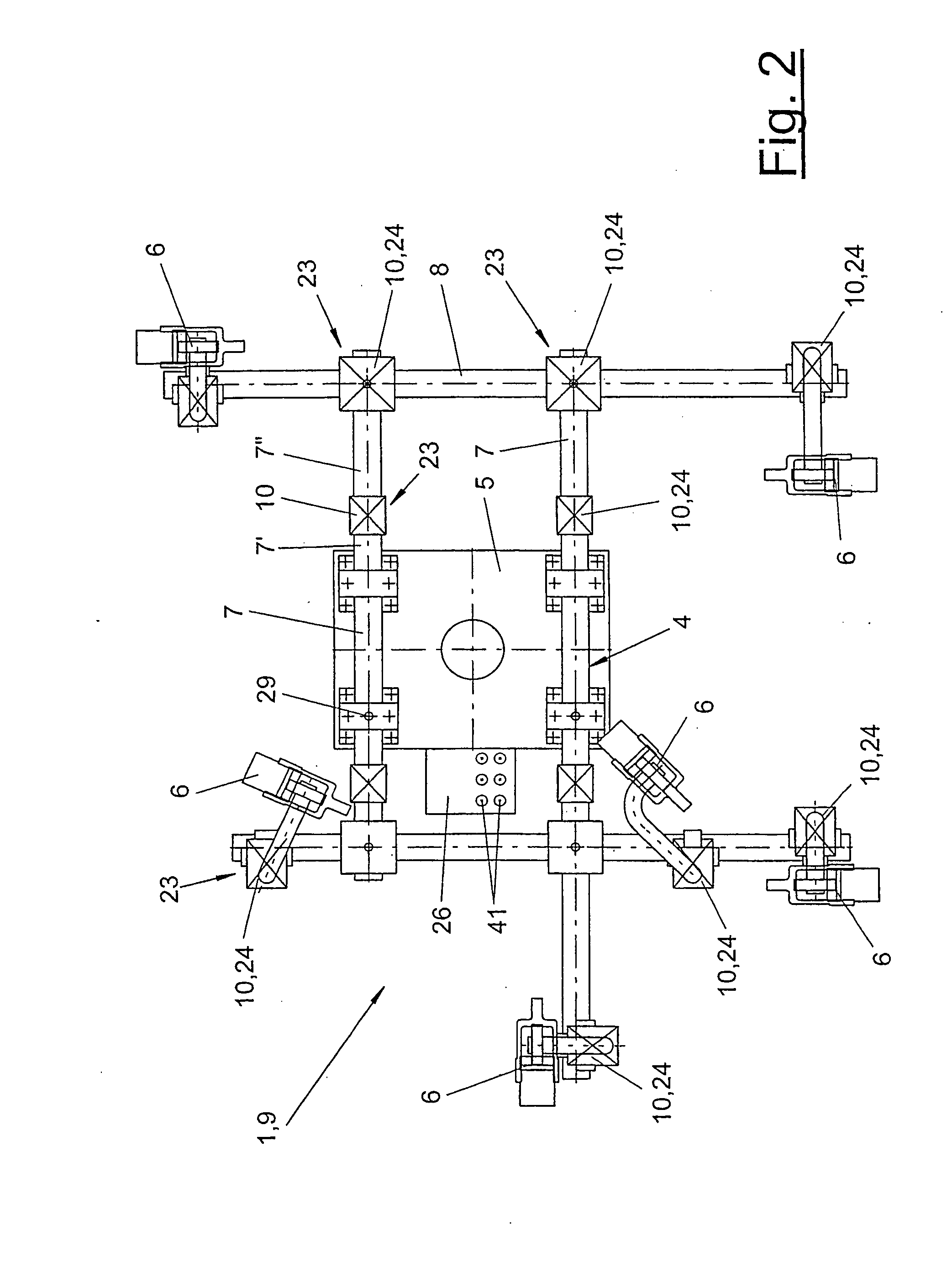
[0006] The deflectable safety device is preferably arranged at a connection point between the different device parts of the gripping device. The device parts, for example, frame tubes, may also be divided, in which case a deflectable safety device is arranged between the tube sections. The deflectable safety device may be located as a result at the points of the gripping device that have been shown by experience to be loaded most heavily and are also critical. Depending on the geometry of the gripping device, the positions of the different deflectable safety devices are selected to be such that the colliding device part can be deflected immediately in case of a collision, and deformations and damage are avoided in this part as well as on the other components of the gripping device.
[0007] The deflectable safety device may connect the device parts with clamping and frictional connection or with deflectable positive-locking connection. An adjusting means makes possible the reproducible positioning of the device parts in the initial device and also during the repositioning after a crash. The detector may be a part of the adjusting means. The moving device part can again be returned into its desired position after the deflection. As a result, the gripping device can continue to be used without complicated measurement and resetting.
[0008] If the deflectable safety device is provided with a locking element for positive-locking guiding, it is thus also possible to exactly define the desired position and to position the device parts. The locking element is preferably spring-loaded, and the overload or load threshold generated by collision, beginning from which deflection is to take place, can be set by means of the spring mounting. The deflectable safety device is rigid and dimensionally stable below this threshold, so that it does not compromise the function and the geometry of the gripping device. The holding frictional force can be set by a controlled clamping connection in case of a frictionally engaged connection.
[0009] From a design viewpoint, the deflectable safety device may have various designs. It preferably comprises at least two safety device parts, which may be designed, for example, as a sphere each with a socket surrounding it or as disk mounts with parallel working surfaces. A plurality of locking elements, which may be designed, for example, as spring-loaded balls or the like, are preferably located between the safety device parts. By selecting the geometry of the safety device parts and of the locking elements correspondingly, the deflectable safety device can make possible deflection along one or more defined axes in case of a collision.

Problems solved by technology

Collisions and crashes may occur here, in which the gripping device may be damaged.
Such damage leads mostly to a change in geometry.
This may also happen due to deformation of the gripper frame.
However, this operates reliably only in case of violent collisions, which propagate to the robot drive.
Minor collisions with weaker forces, which are mostly absorbed extensively by the yielding of the gripping device or parts thereof, cannot be recognized by monitoring the motor current.
However, such minor collisions nevertheless lead to damage to and malfunction of the gripping device, which in turn entails errors in the machining process and on the body shell.
This is a very complicated operation and can be carried out only outside the gripper operation.

Method used


Image

  • Manipulator-guided gripping device having a deflection safety device that can prevent collisions
  • Manipulator-guided gripping device having a deflection safety device that can prevent collisions
  • Manipulator-guided gripping device having a deflection safety device that can prevent collisions

Examples


Embodiment Construction

[0023] Referring to the drawings in particular, FIG. 1 shows a schematic side view of a machining station for workpieces, which are held and guided by a mechanical manipulator (2) by means of a gripping device (1). The workpiece, which is not shown for clarity's sake, may be of any desired type whatsoever. It is preferably a body part of a body shell, for example, a side panel part or the like. The manipulator (2) is preferably designed as a multiaxial industrial robot, especially as a six-axis articulated arm robot. The workpieces can be picked up, transported, brought into defined positions and locations and aligned as well as again deposited with the gripping device (1). These manipulation processes can take place fully automatically by means of a control (26). This is, e.g., a process control, which is integrated in the robot control. As an alternative, it may also be arranged externally. It may also be located at the gripping device (1) according to FIG. 2.

[0024]FIG. 2 shows a...


PUM


Abstract

A manipulator-guided gripping device (1) for motor vehicle body parts includes a number of device parts (6, 7) and a safety device (9), which serves to determine geometrical changes of the device parts (6, 7, 8). At least one deflection safety device (10), which prevents collisions, is provided on the device parts (6, 7, 8). The deflection safety device (10) is mounted on a junction point (23) between the device parts (6, 7, 8).

Description

CROSS REFERENCE TO RELATED APPLICATIONS [0001] This application is a United States National Phase application of International Application PCT / EP2004 / 006113 filed Jun. 7, 2004 and claims the benefit of priority under 35 U.S.C. § 119 of German Application DE 203 09 435.2 filed Jun. 17, 2003 and DE 203 14 896.7 filed Sep. 24, 2003, the entire contents of which are incorporated herein by reference.FIELD OF THE INVENTION [0002] The present invention pertains to a manipulator-guided gripping device for workpieces, especially body parts in the body shell, wherein the gripping device has a plurality of device parts and a safety means for detecting changes in geometry. BACKGROUND OF THE INVENTION [0003] Such a gripping device for vehicle body parts in body framing and paneling is known from DE 200 04 369 U1. The gripping device is guided by a multiaxial industrial robot. Such devices are used in partially or fully automatic plants or cells for body framing and paneling or in other technical...

Claims


Application Information

Patent Timeline
IPC IPC(8): A47G21/10B25J15/00B25J19/06
CPCB25J15/0052B25J19/063B25J15/0061
Inventor KIKUT, BOTHONUCHTER, ELMAR
Owner KUKA SYSTEMS
Features
  • Generate Ideas
  • Intellectual Property
  • Life Sciences
  • Materials
  • Tech Scout
  • Unparalleled Data Quality
  • Higher Quality Content
  • 60% Fewer Hallucinations
Learn More