Cylindrical linear motor, electromagnetic suspension, and vehicle using the same

Inactive Publication Date: 2006-08-17
HITACHI LTD
View PDF9 Cites 54 Cited by
  • Summary
  • Abstract
  • Description
  • Claims
  • Application Information

AI Technical Summary

Benefits of technology

[0018] According to the present invention, it is possible to generat

Problems solved by technology

However, the electromagnetic suspension disclosed in JP-A-2004-53003 has the problem as follows.
Also, the electromagnetic suspension disclosed in JP-A-7-276963 has the problem that, because of the structure having no magnet on the slider side, an electromotiv

Method used


Image

  • Cylindrical linear motor, electromagnetic suspension, and vehicle using the same
  • Cylindrical linear motor, electromagnetic suspension, and vehicle using the same
  • Cylindrical linear motor, electromagnetic suspension, and vehicle using the same

Examples


Embodiment Construction

[0029] The structure of an electromagnetic suspension according to an embodiment of the present invention will be described below with reference to FIGS. 1-6.

[0030] First, the structure of a cylindrical linear motor used in the electromagnetic suspension of the embodiment will be described with reference to FIGS. 1 and 2.

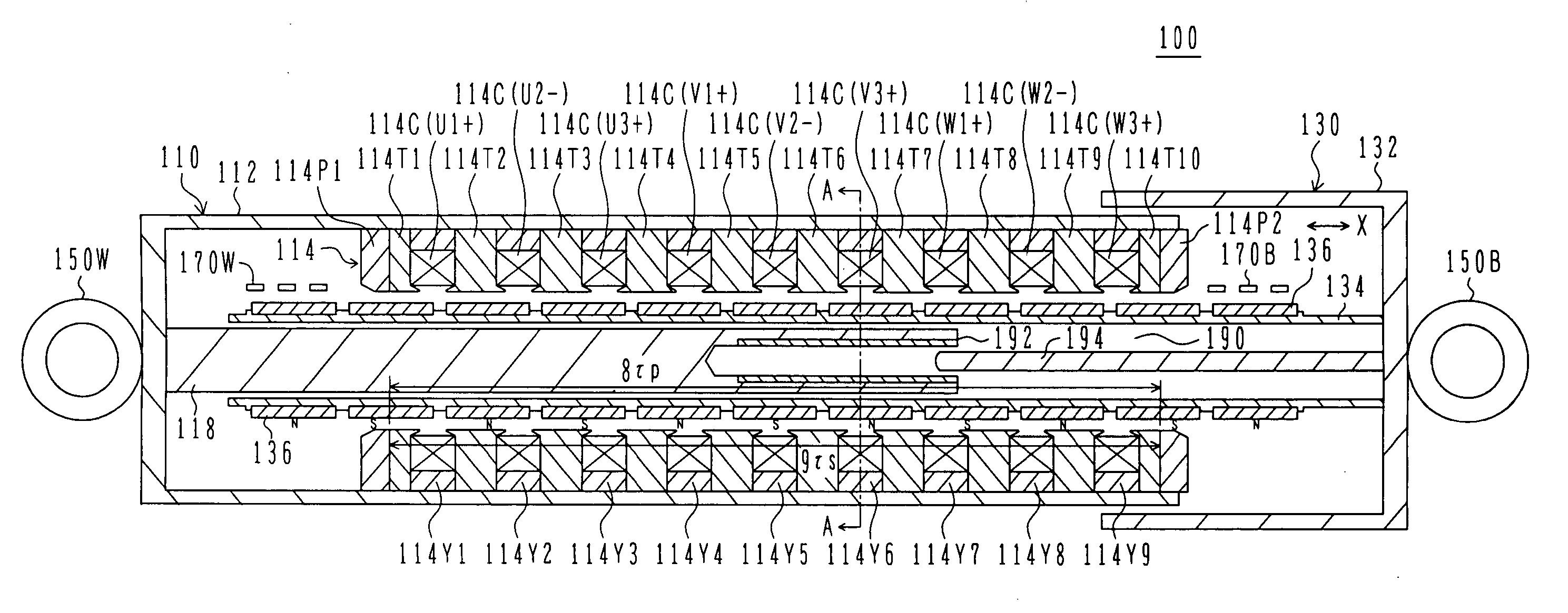
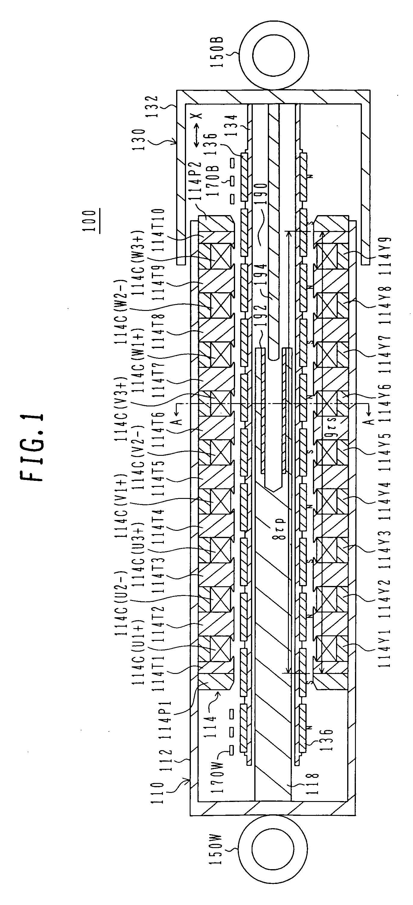
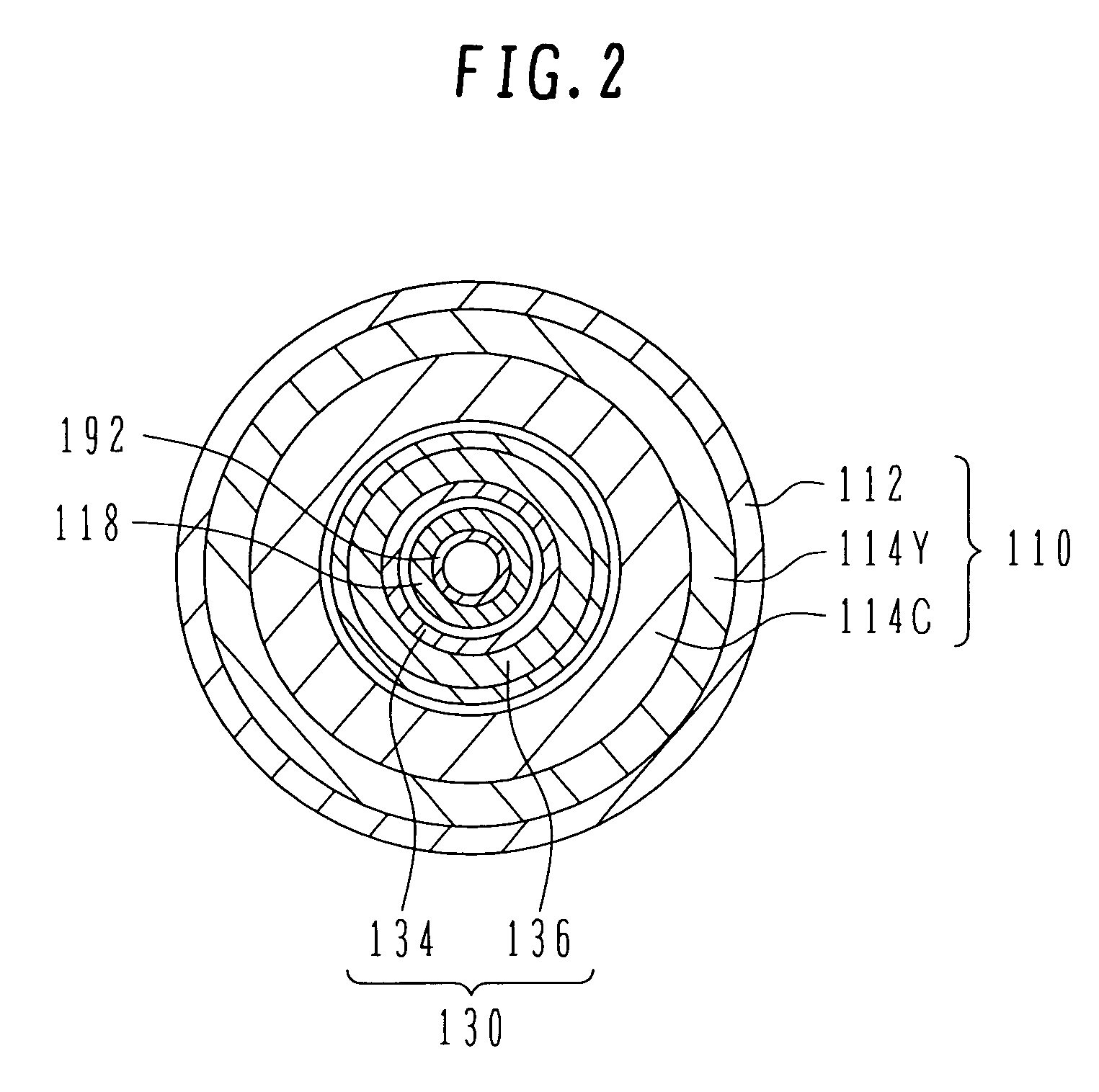
[0031]FIG. 1 is a longitudinal sectional view showing the structure of the cylindrical linear motor used in the electromagnetic suspension according to the embodiment. FIG. 2 is a sectional view taken along the line A-A in FIG. 1.

[0032] A permanent magnet type 3-phase cylindrical linear motor 100 of the embodiment comprises a cylindrical stator 110 and a cylindrical slider 130 held inside the stator 110 in a slidable manner.

[0033] The stator 110 comprises a stator case 112, a stator core 114, stator windings 114C, and a stator inner case 118. The stator case 112 has a cylindrical shape provided with the bottom, and a mounting portion 150W is fixed to an outer en...


PUM


Abstract

A cylindrical linear motor, an electromagnetic suspension, and a vehicle using the same, which can generate a large thrust and reduce torque pulsations and cogging torque. The cylindrical linear motor comprises a stator and a slider disposed with a gap left relative to the stator and being linearly movable relative to the stator. The stator comprises a stator core having stator salient poles, and 3-phase stator windings inserted in slots formed in the stator core. The slider comprises a plurality of permanent magnets fixed to a slider core. The motor satisfies τp:τs=9:9±1 where τs is a pitch of the stator salient poles and τp is a pitch of the permanent magnets.

Description

BACKGROUND OF THE INVENTION [0001] 1. Field of the Invention [0002] The present invention relates to a cylindrical linear motor, an electromagnetic suspension, and a vehicle using the same. [0003] 2. Description of the Related Art [0004] In one known example of electromagnetic suspensions disclosed in JP-A-2004-53003 (Patent Document 1), a 3-phase synchronous cylindrical linear motor is used as a motor for an electromagnetic suspension. The 3-phase synchronous cylindrical linear motor has a structure that coils are mounted to the inner peripheral side of an outer cylinder (stator) of a double cylinder, and a magnet is mounted to the outer peripheral side of an inner cylinder (slider). A stator core is not used. [0005] JP-A-7-276963 (Patent Document 2) discloses another known example in which a 3-phase asynchronous (inductive) cylindrical linear motor comprising a stator core formed of a ring-shaped spacer and a stator formed of coils is used as a motor for an electromagnetic suspens...

Claims


Application Information

Patent Timeline
IPC IPC(8): H02K41/00
CPCB60G17/0157H02K41/03
Inventor TAJIMA, FUMIOKITAMURA, MASASHIKIM, HOUNGJOONGAKAMI, YUSUKEUTSUMI, NORIYUKINAKAMURA, KENSHIBAHARA, KAZUAKI
Owner HITACHI LTD
Why Eureka
Try Eureka