

Magnetic resonance imaging apparatus and its control method
a magnetic resonance imaging and control method technology, applied in the field of magnetic resonance imaging apparatus, can solve the problems of reducing the signal-to-ratio (snr), degrading the quality of the resultant image, and difficult for users to determine whether the image quality is deteriorating
- Summary
- Abstract
- Description
- Claims
- Application Information
AI Technical Summary
Benefits of technology
Problems solved by technology
Method used
Image

Examples
first embodiment
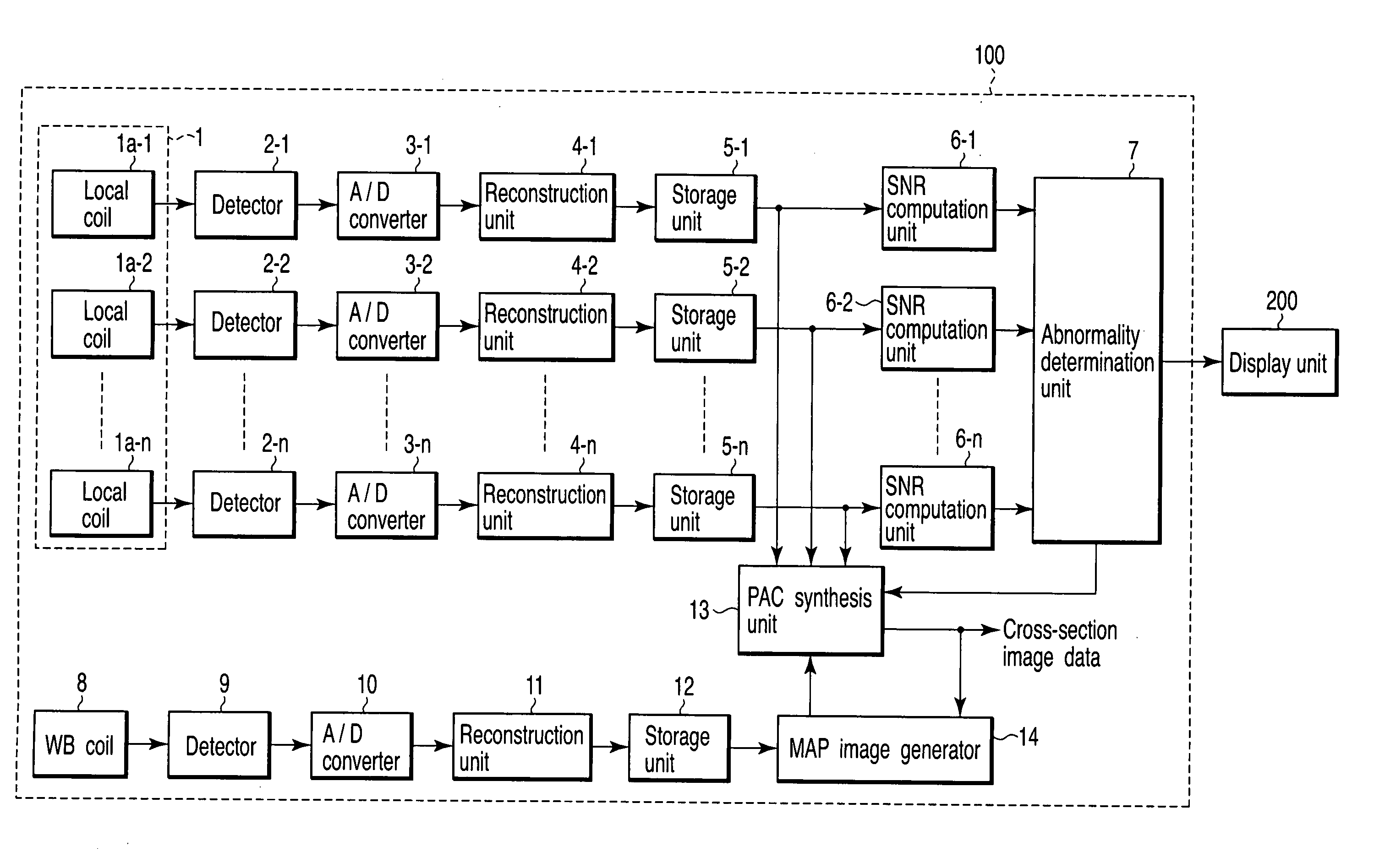
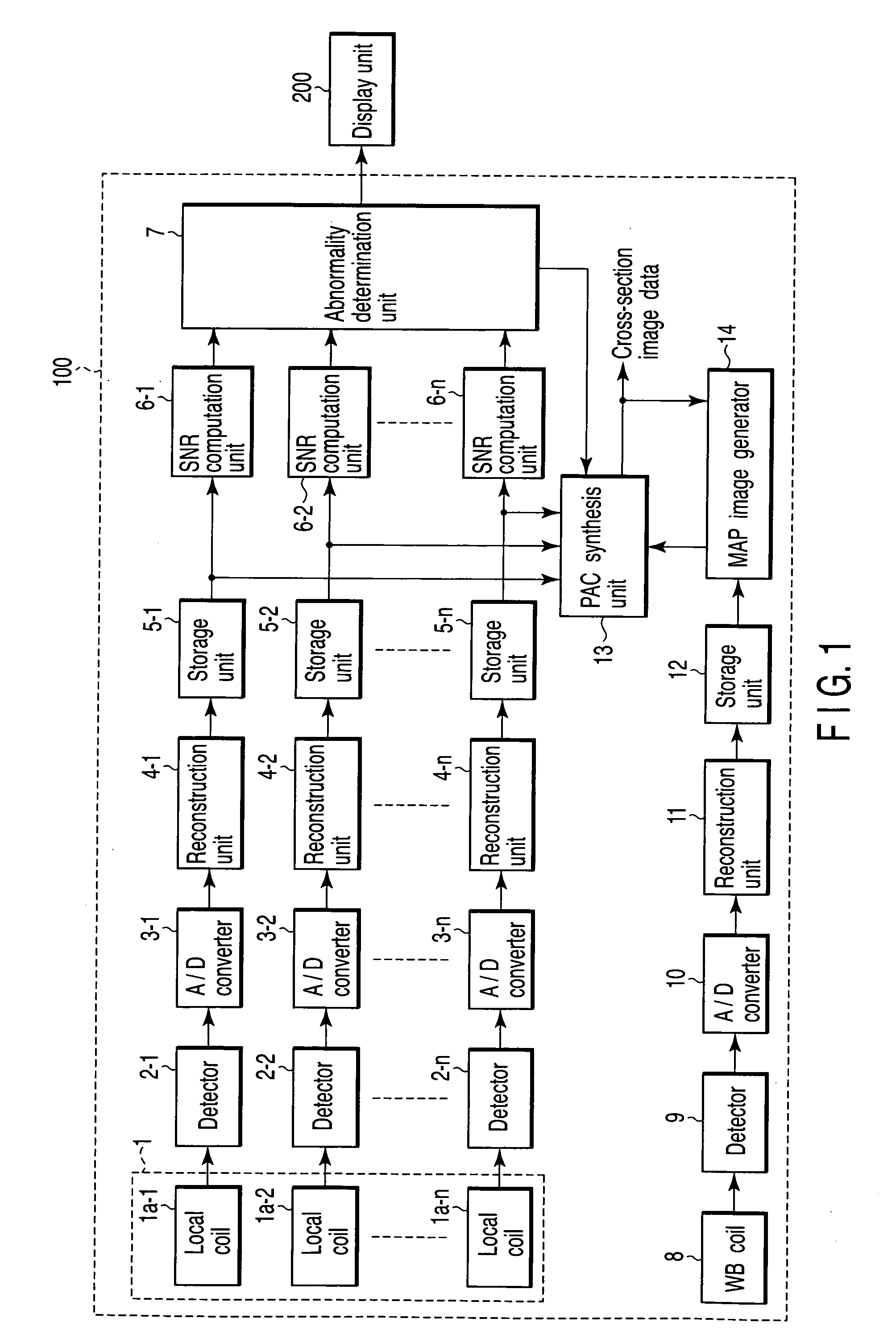
[0024]FIG. 1 is a block diagram illustrating the configuration of the basic components of a magnetic resonance imaging (MRI) apparatus 100 according to a first embodiment of the invention. Although various components similar to those employed in known MRI apparatuses are employed in the MRI apparatus 100, as well as the components shown in FIG. 1, they are not shown or described.
[0025] As shown in FIG. 1, the MRI apparatus 100 comprises a phased array coil 1, detectors 2-1, 2-2, . . . , 2-n, A / D (analog-to-digital) converters 3-1, 3-2, . . . , 3-n, reconstruction units 4-1, 4-2, . . . , 4-n, storage units 5-1, 5-2, . . . , 5-n, SNR computation units 6-1, 6-2, . . . , 6-n, abnormality determination unit 7, whole body coil (WB coil) 8, detector 9, A / D converter 10, reconstruction unit 11, storage unit 12, PAC synthesis unit 13 and MAP image generator.
[0026] The phased array coil 1 includes a plurality of local coils 1a-1, 1a-2, . . . , 1a-n. Each combination of corresponding ones of...
second embodiment
[0058]FIG. 5 is a block diagram illustrating the configuration of the basic components of an MRI apparatus 300 according to a second embodiment. The greater part of the MRI apparatus 300 is similar to the MRI apparatus 100. FIG. 5 shows only components different from those of the MRI apparatus 100. In FIG. 5, elements similar to those of FIG. 1 are denoted by corresponding reference numbers, and no detailed descriptions will be given thereof.
[0059] The MRI apparatus 300 differs from the MRI apparatus 100 only in that the former employs a phased array coil including quadrature coils (QD coils) as local coils, instead of the phased array coil 1. FIG. 5 only shows a processing system corresponding to one channel incorporated in the phased array coil. Namely, in the MRI apparatus 300, the processing system corresponding to one channel comprises a detector 2, A / D converter 3, reconstruction unit 4, storage units 5, SNR computation units 6, QD coil 21, peak hold units 22 and 23 and inten...
third embodiment
[0072]FIG. 7 is a block diagram illustrating the configuration of the basic components of an MRI apparatus 400 according to a third embodiment. The greater part of the MRI apparatus 400 is similar to the MRI apparatus 100. In FIG. 7, elements similar to those of FIG. 1 are denoted by corresponding reference numbers, and no detailed descriptions will be given thereof.
[0073] As can be seen from FIG. 7, the MRI apparatus 400 comprises a phased array coil 1, detectors 2-1, 2-2, . . . , 2-n, A / D converters 3-1, 3-2, . . . , 3-n, reconstruction units 4-1, 4-2, . . . , 4-n, storage units 5-1, 5-2, . . . , 5-n, whole body coil (WB coil) 8, detector 9, A / D converter 10, reconstruction unit 11, storage unit 12, PAC synthesis unit 13, MAP image generator 14, intensity-ratio computation units 31-1, 31-2, . . . , 31-n and abnormality determination unit 32. Namely, the MRI apparatus 400 incorporates the intensity-ratio computation units 31-1, 31-2, . . . , 31-n and abnormality determination unit...
PUM
 Abstract
Description
Claims
Application Information