Systems for dynamically illuminating touch sensors

a touch sensor and dynamic illumination technology, applied in the field of electronic input devices, can solve the problems of limited space, difficult customization of portable devices that use touch sensors, and little room for indicators, and achieve the effect of saving power and being convenient to loca

Inactive Publication Date: 2006-08-17
AUTHENTEC
View PDF36 Cites 211 Cited by
  • Summary
  • Abstract
  • Description
  • Claims
  • Application Information

AI Technical Summary

Benefits of technology

[0005] The present invention is directed to systems for and methods of indicating the status of touch sensors. An exemplary system of the present invention uses a dynamic illuminator positioned next to a contact surface of the touch sensor and used to display the status of the touch sensor. The displayed status can indicate, for example, that the touch sensor is (1) in standby mode, thereby conserving power; (2) in power on mode; (3) waiting to receive input, that is, ready to be contacted by a finger to launch a function or to verify a user's identity; (4) currently functioning as a scroll wheel; or (4) currently functioning as a push button, to name a few statuses. Preferably, the dynamic illuminator is positioned near or even surrounds a contact area of the touch sensor so that the touch sensor can be easily located in a darkened room.

Problems solved by technology

This limited space leaves little room for indicators to show whether the touch sensor is operating correctly, whether it is being used as a menu navigator or as a scroll wheel, or whether it is in power on or standby mode, to name a few possible statuses of the touch sensor.
Furthermore, it is difficult to customize portable devices that use touch sensors to indicate the status of the touch sensors.
For example, when a cell phone incorporates a touch sensor, it is costly to configure the cell phone so that its LCD displays the status of the touch sensor.

Method used


Image

  • Systems for dynamically illuminating touch sensors
  • Systems for dynamically illuminating touch sensors
  • Systems for dynamically illuminating touch sensors

Examples


Embodiment Construction

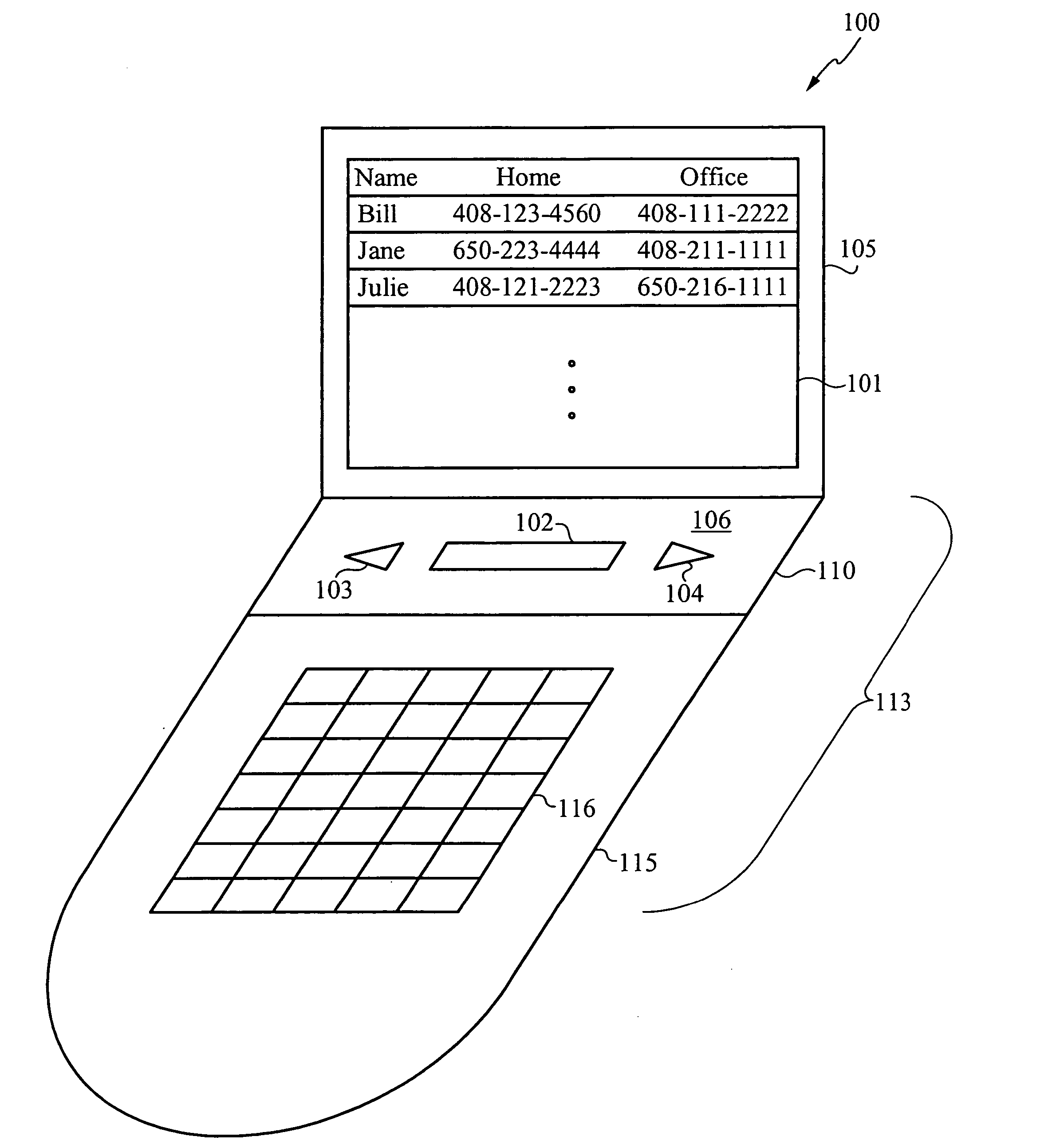
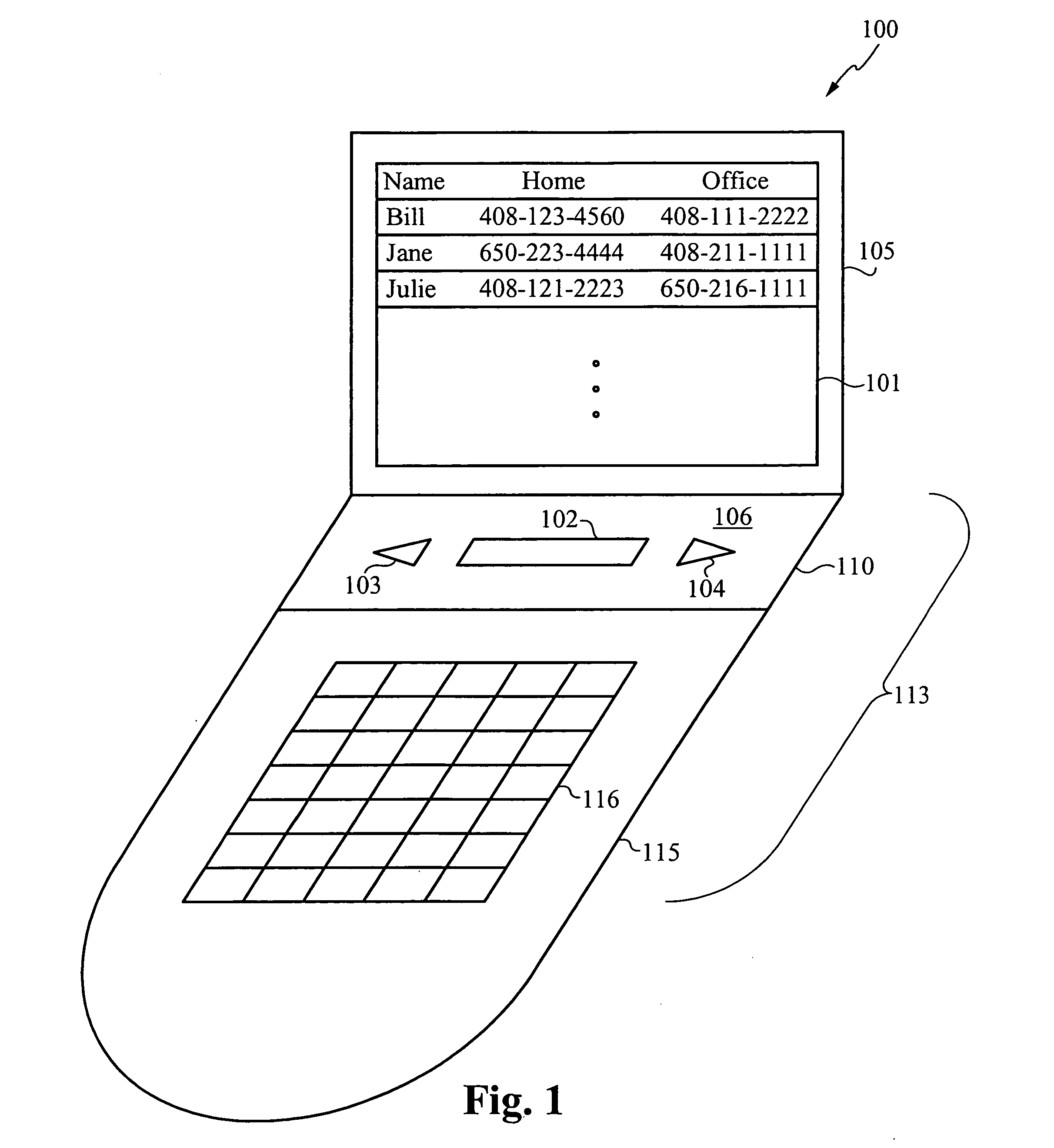
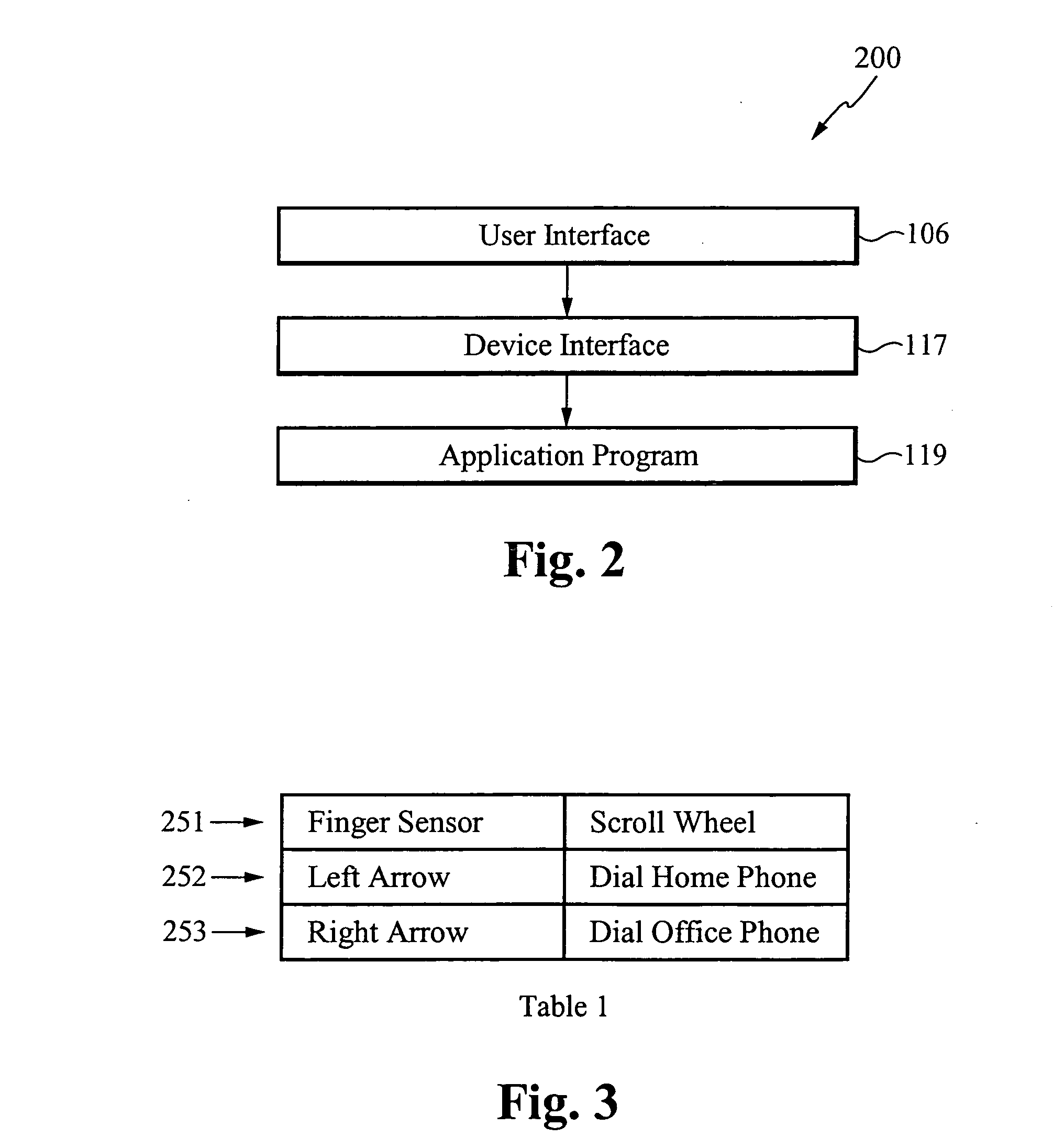
[0033] In accordance with the present invention, a status of a touch sensor system is indicated by a dynamic illuminator that preferably includes multiple light channels. By illuminating combinations of light channels from multiple light sources or channels, the dynamic illuminator indicates that the touch sensor system is powered on, powered off, in a standby mode, has encountered an error, in an input mode in which it is waiting for user input, in an operating mode, in which it is emulating an input device such as a mouse, a scroll wheel, a push button, a joy stick, a cursor, and a pressure button, to name a few input devices. The light channels can be clear to accurately show the color of the illumination or colored to alter the light it channels.

[0034] As used herein, the term “touch sensor” is used generally to mean any device that functions by being contacted. Touch sensors accordingly include, but are not limited to, fingerprint sensors, including fingerprint swipe sensors a...


PUM


Abstract

A system for and method of illuminating a contact (or touch) device such as a fingerprint sensor are disclosed. In an exemplary system, a touch sensor system has a surface or contact area and comprises a substantially transparent molding positioned over the contact area and a dynamic illuminator positioned to show through the molding. The dynamic illuminator is for indicating a status of the touch sensor system, such as power on, standby, error, low power, an input mode for receiving user input, or a selected operating mode. The touch sensor system includes any one of a fingerprint sensor, a miniature joystick, a touch-sensitive navigation disc, a touch-sensing navigation pad, an N-way pressure-sensitive directional control, to name a few touch sensor devices. In one embodiment, when the touch sensor comprises a fingerprint sensor, the operating mode is for emulating an input device such as a scroll wheel, a push button, a steering wheel, a joy stick, a pressure button, and a mouse. The operating mode also includes an authentication mode for authenticating an identity of a user. Preferably, the dynamic illuminator includes light sources and multiple light channels, colored or not, that are configured to be illuminated in multiple configurations, where each configuration corresponds to a status of the touch sensor system.

Description

RELATED APPLICATIONS [0001] This application claims priority under 35 U.S.C. § 119(e) of the co-pending U.S. provisional patent application Ser. No. 60 / 669,520, filed Apr. 8, 2005, and titled “Dynamically Illuminated Biometric Sensor, Modular Packaging Technology, and Over-Current Chip Protection Architecture,” which is hereby incorporated by reference. This application is also a continuation-in-part application of the co-pending U.S. patent application Ser. No. 11 / 058,514, filed Feb. 14, 2005, and titled “A Customizable Touch Input Module for an Electronic Device,” which is also hereby incorporated by reference.FIELD OF THE INVENTION [0002] The present invention relates to electronic input devices. More particularly, the present invention relates to systems for and methods of illuminating touch sensors. BACKGROUND OF THE INVENTION [0003] Touch sensors are used on an ever increasing number of electronic devices. Touch sensors include joy sticks, pressure sensors, navigation buttons,...

Claims


Application Information

Patent Timeline
Patent Type & Authority Applications(United States)
IPC IPC(8): G09G5/00G06V40/13
CPCG06F1/1613G06F1/1684G06F1/169G06F3/0202G06F3/0338G06F3/03547G06F3/0488G06F2203/0338G06F2203/0339G06K9/00013H04M1/22H04M1/274508H04M1/274525H04M1/72522H04M1/2747H04M1/27453H04M1/72403Y02D30/70G06V40/13
Inventor PERREAULT, GEORGEGIOELI, ANTHONY
Owner AUTHENTEC
Why Eureka
Try Eureka