Reflected backdrop display and telepresence network
What is Al technical title?
Al technical title is built by PatSnap Al team. It summarizes the technical point description of the patent document.
a technology of reflected backdrop and telepresence network, which is applied in the field of video teleconferencing devices, can solve the problems of reducing affecting the quality of the conferencing experience, and awkward positioning of the camera
Inactive Publication Date: 2006-08-17
VIDEOTRONIC SYST
View PDF42 Cites 149 Cited by
Summary
Abstract
Description
Claims
Application Information
AI Technical Summary
This helps you quickly interpret patents by identifying the three key elements:
Problems solved by technology
Method used
Benefits of technology
[0036] The present invention enables eye contact between conferees during a teleconference using a terminal equipped with a beamsplitter for reflecting an image of a conferee. In one embodiment the image of the conferee appears to be in a backdrop. The display is positioned behind the viewing side of the beam-splitter so that the conferee views the display through the beamsplitter. The invention can be configured to create the appearance that a life-size teleconference image of a remote conferee appears in the same room as the local conferee apparently sitting on the other side of the desk or table-creating the experience of telepresence with eye contact. Additional embodiments include adaptable features of the present invention which enable it to be configured into many specific types of eye contact display products. The invention further teaches the design of a telepresence network linking numerous terminals sharing a commonality in configuration. The invention also includes many additional versatility embodiments for desktop and group videoconferencing, as well as other videoconferencing applications.
Problems solved by technology
The drawbacks to this arrangement include the increased bulk of the terminal (although a flat panel will minimize this problem), the addition of a transparent barrier in front of the display which affects viewing the display surface, the appearance of the display being recessed far into the terminal creating a tunnel effect and, lastly, the awkward positioning of the camera 4 which intrudes into the conferee's work space.
As is illustrated, the significant drawback of this arrangement is the fact that the light from the display 2 is visible to the conferee simultaneously at the display 2 and as the reflection of the display 2 in the beamsplitter 6 by the conferee.
These two visible images compete for the conferee's attention and add distraction while conferencing, thereby reducing the quality of the conferencing experience.
Method used
Image
Click on the blue label to locate the original text in one second.
Reading with bidirectional positioning of images and text.
Examples
Embodiment Construction
[0200] The following description is provided to enable any person skilled in the art to make and use the invention and sets forth the best modes contemplated by the inventor of carrying out his invention. Various modifications, however, will remain readily apparent to those skilled in the art, since the general principles of the present invention have been defined herein specifically to provide an improved beamsplitter-based teleconferencing device.
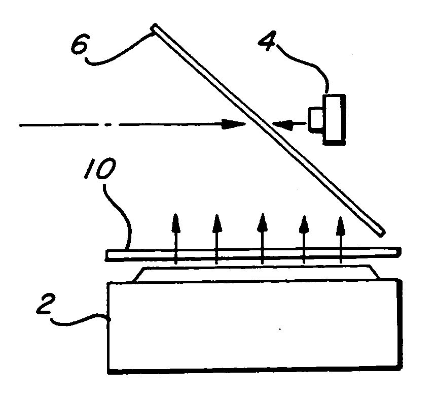
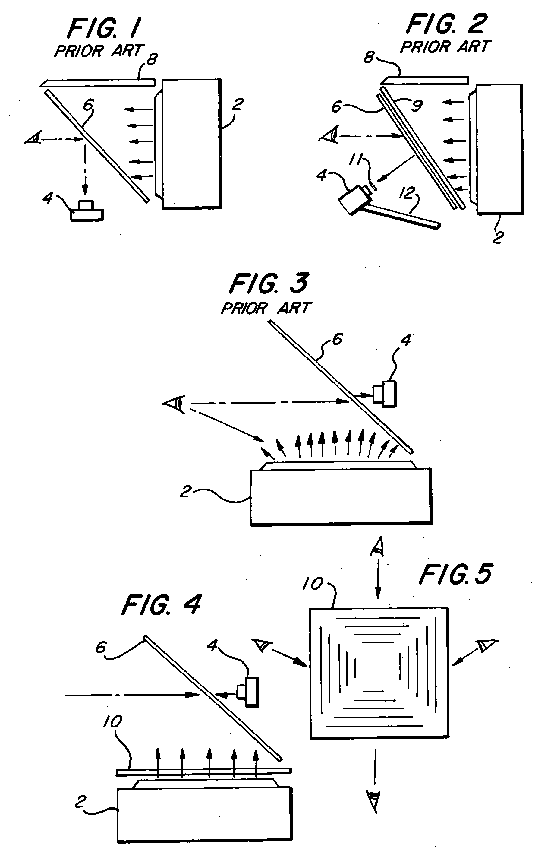
[0202] An eye contact beamsplitter arrangement has been invented to overcome the problem of a conferee simultaneously viewing both the display and its reflection. An image blocking film 10 permits a display 2 to be viewed from one or more directions and prevents the interference of unwanted images. As seen in FIG. 4, a conferee can view the reflection from the display 2 on a beamsplitter 6. The conferee cannot, however, see the display 2 emitted directly, because direct light is bloc...
PUM
Abstract
The present invention enables eye contact between conferees during a teleconference using a terminal equipped with a beamsplitter for reflecting an image of a conferee. In one embodiment the image of the conferee appears to be in a backdrop. The display is positioned behind the viewing side of the beam-splitter so that the conferee views the display through the beamsplitter. The invention can be configured to create the appearance that a life-size teleconference image of a remote conferee appears in the same room as the local conferee apparently sitting on the other side of the desk or table—creating the experience of telepresence with eye contact. Additional embodiments include adaptable features of the present invention which enable it to be configured into many specific types of eye contact display products. The invention further teaches the design of a telepresence network, linking numerous terminals sharing a commonality in configuration. The invention also includes many additional versatility embodiments for desktop and group videoconferencing, as well as other videoconferencing applications.
Description
CROSS-REFERENCE TO PRIOR APPLICATIONS [0001] The present application is a Continuation-In-Part of application Ser. No. 10 / 785,820 (Feb. 24, 2004) which is a Continuation In Part of application Ser. No. 10 / 033,655 (27 Dec. 2001) which is a Continuation In Part of application Ser. No. 09 / 878,813, now issued as U.S. Pat. No. 6,481,651, which is, in turn, a Continuation In Part of application Ser. No. 09 / 777,145 (5 Feb. 2001), now abandoned, which is a Continuation In Part of application Ser. No. 09 / 262,974 (5 Mar. 1999), now issued as U.S. Pat. No. 6,243,130, which is a Continuation In Part of application Ser. No. 09 / 108,476, (1 Jul. 1998), now issued as U.S. Pat. No. 5,953,052, which is a Continuation In Part of Ser. No. 08 / 530,880, (20 Sep. 1995), and now issued as U.S. Pat. No. 5,777,665 which applications are hereby incorporated by reference into this application.U.S. GOVERNMENT SUPPORT [0002] NA BACKGROUND OF THE INVENTION [0003] 1. Area of the Art [0004] The present invention con...
Claims
Application Information
Patent Timeline
Application Date:The date an application was filed.
Publication Date:The date a patent or application was officially published.
First Publication Date:The earliest publication date of a patent with the same application number.
Issue Date:Publication date of the patent grant document.
PCT Entry Date:The Entry date of PCT National Phase.
Estimated Expiry Date:The statutory expiry date of a patent right according to the Patent Law, and it is the longest term of protection that the patent right can achieve without the termination of the patent right due to other reasons(Term extension factor has been taken into account ).
Invalid Date:Actual expiry date is based on effective date or publication date of legal transaction data of invalid patent.
Patent Type & Authority Applications(United States)