Belt driving control apparatus and image forming apparatus

a control apparatus and belt technology, applied in the direction of electrographic process apparatus, instruments, optics, etc., can solve the problems of low precision, inability to implement control with high precision, and degrade image quality, and achieve stable speed variation, simple structure, and secure construction

Active Publication Date: 2006-08-17
RICOH KK
View PDF5 Cites 24 Cited by
  • Summary
  • Abstract
  • Description
  • Claims
  • Application Information

AI Technical Summary

Benefits of technology

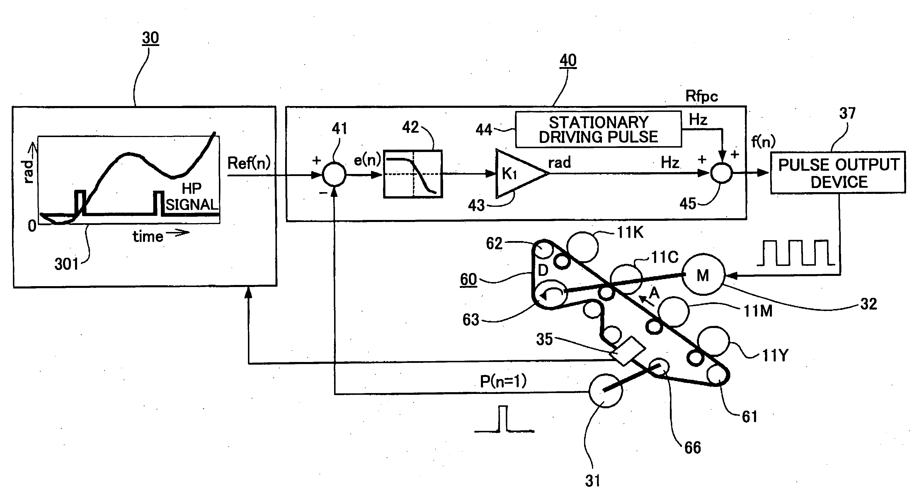
[0065] According to the above-discussed driving control apparatus or image forming apparatus, stability of speed variation generated by the change of the belt thickness can be securely made in a simple structure in a case where the conveyance speed of the endless belt wound around the driving roller and the idler roller is controlled by using a detection signal by the encoder attached to the idler roller. In addition, it is possible to perform proper processing corresponding to image quality so that good feed back control can be done.

Problems solved by technology

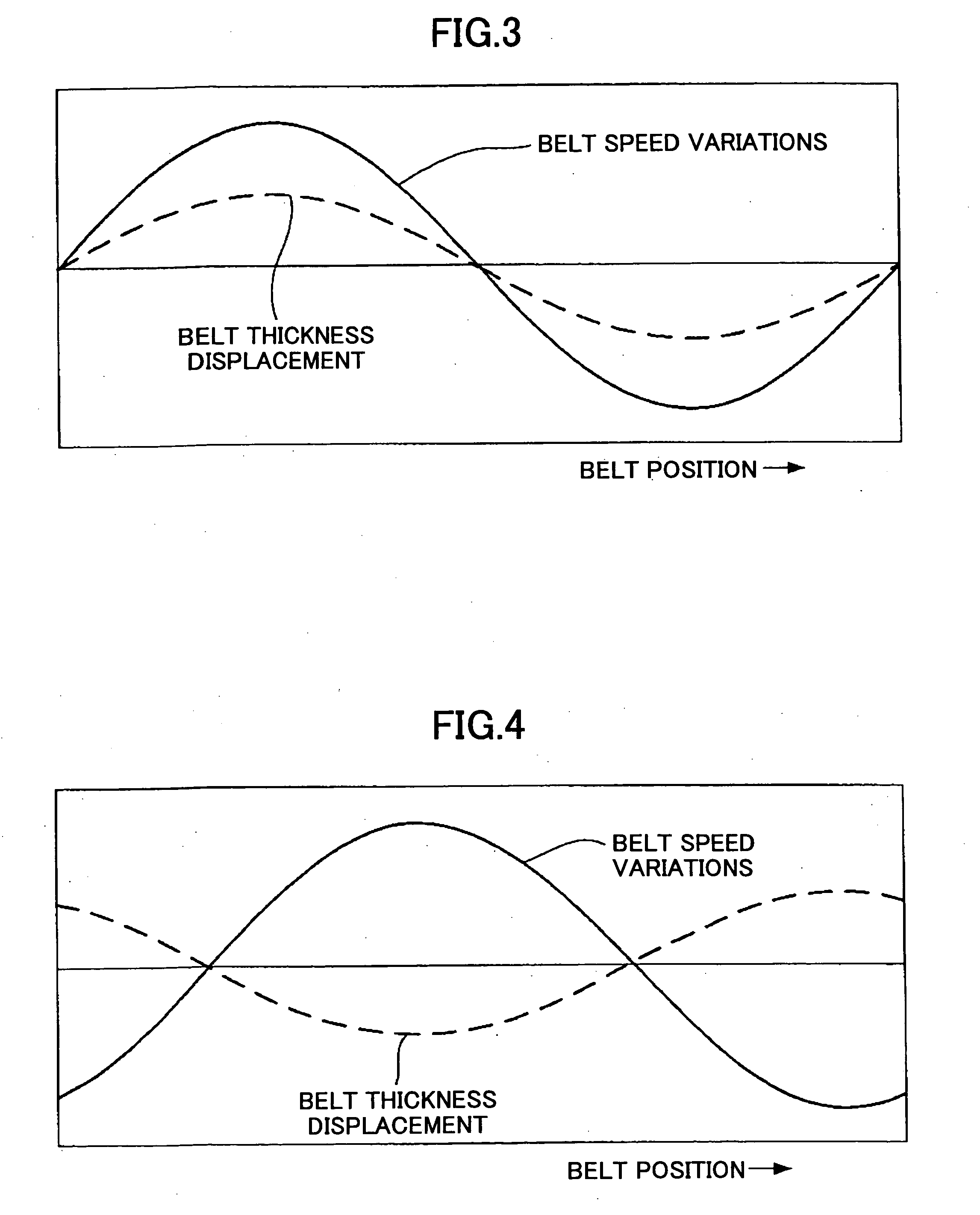
However, in this method, the conveyance speed of the transferring paper is changed due to the minute thickness of the conveyance belt so that the image is shifted from the ideal position and the image quality is degraded.
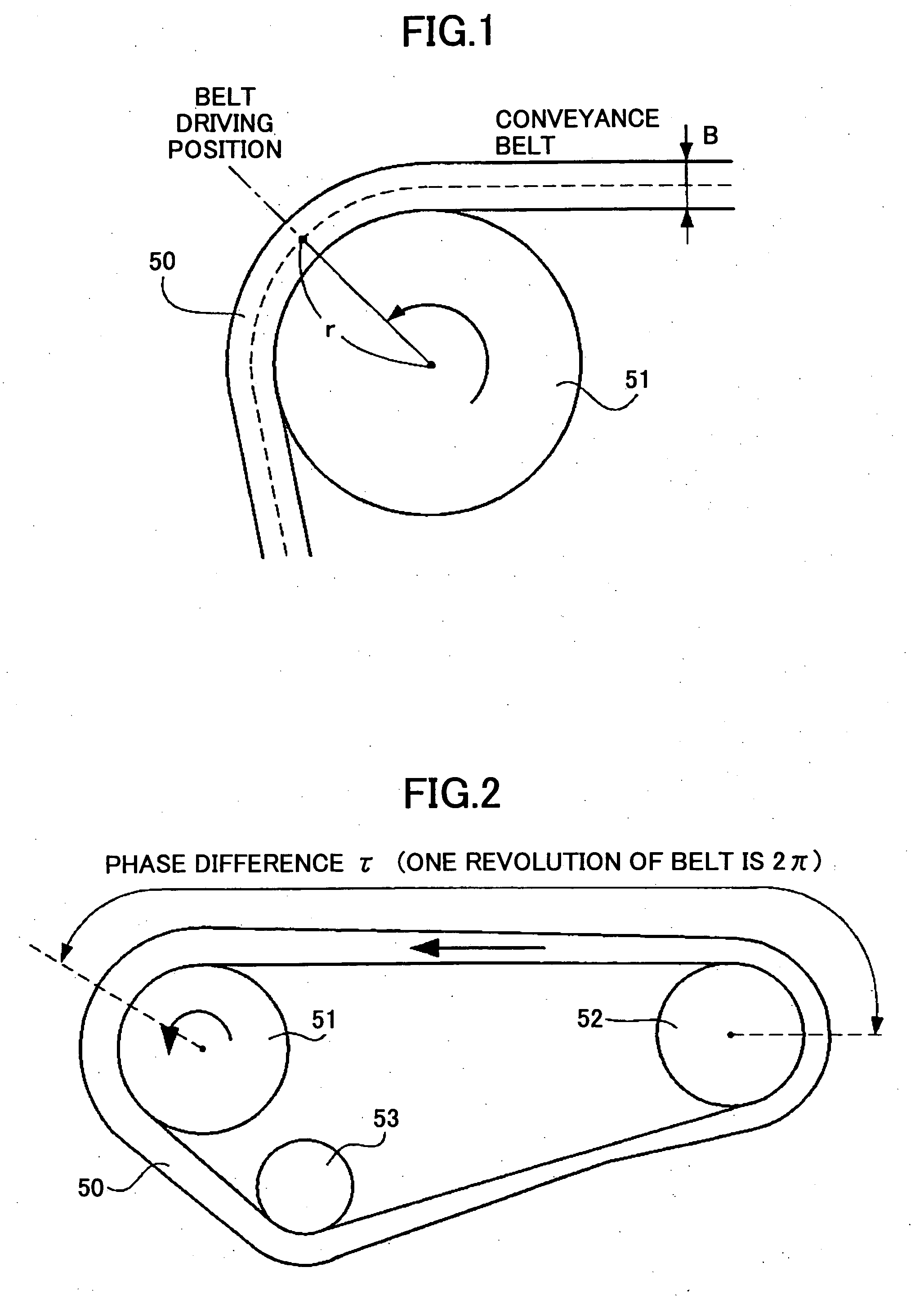
Thus, in a case where the thickness of the belt is changed, if the belt conveyance speed is detected by the angular displacement of the idler roller by using an encoder or the like, an error detection element is generated.
In addition, in the above-mentioned dependent shaft feed back control, it is not possible to implement the control with high precision considering such a belt thickness displacement.
Hence, in a case where the control cycle is a short cycle, a large amount memory is required.
In addition, in a case where the control cycle is a short cycle, the feed back control per se cannot obtain a sufficient effect.
Even if data are compressed and stored, and the data are expanded and loaded in a volatile memory at the time when the electric power is turned on, the large amount memory is still necessary.
Because of this, a separate memory in addition to the memory used as a normal work area is necessary so that an undesirable large increase of the cost happens.
In addition, data management of the measured result is complex.
Furthermore, since the amount of data is large, an input error may be generated.

Method used


Image

  • Belt driving control apparatus and image forming apparatus
  • Belt driving control apparatus and image forming apparatus
  • Belt driving control apparatus and image forming apparatus

Examples


Embodiment Construction

[0097] A description of the present invention is now given, with reference to FIG. 5 through FIG. 30, including embodiments of the present invention.

[0098] First, with reference to FIG. 6 and FIG. 7, a structural example of an image forming apparatus having a belt driving control apparatus of an embodiment of the present invention is discussed. A color laser printer (hereinafter “laser printer”) forming a color image by using an electrophotographic method of a direct transferring method is an example of the image forming apparatus.

[0099]FIG. 6 is a schematic structural diagram of a laser printer of an example of an image forming apparatus having the belt driving control apparatus of the embodiment of the present invention.

[0100] In this laser printer, as shown in FIG. 6, four toner image forming parts 1Y, 1M, 1C and 1K are arranged in turn from an upstream side (right lower side in FIG. 6) in a direction which the transferring paper P is moved by moving the belt 60 along an arrow...


PUM


Abstract

A belt driving control apparatus, the belt driving control apparatus having an endless belt, a driving roller driving the endless belt, a driving motor driving the driving roller, at least one idler roller being dependent on the endless belt, and an encoder attached to one of the idler roller, the belt driving control apparatus includes a structure where a control target value of the driving motor is set so that an effective speed of the endless belt is constant and the driving motor is drive-controlled so that the control target value is satisfied.

Description

BACKGROUND OF THE INVENTION [0001] 1. Field of the Invention [0002] The present invention generally relates to belt driving control apparatuses and image forming apparatuses, and more specifically to a belt driving apparatus configured to control driving of an endless belt such as a transferring conveyance belt used for a transferring apparatus or the like of a color image forming apparatus, and an image forming apparatus, such as a color printer or color copier, having the belt driving control apparatus. [0003] 2. Description of the Related Art [0004] There are two methods, a direct transferring method and an intermediate transferring method, as general methods for forming a color image in an image forming apparatus. In the direct transferring method, toner images having different colors and formed on plural photosensitive bodies are directly superposed (overlapped) on a transferring paper so that transferring is made. In the intermediate transferring method, the toner images havin...

Claims


Application Information

Patent Timeline
Patent Type & Authority Applications(United States)
IPC IPC(8): G03G15/01
CPCG03G2215/0119G03G15/0194G03G2215/0193G03G2215/0158
Inventor OKAMURA, HIROSHIMATSUDA, YUJIMATSUDA, HIROMICHIANDOH, TOSHIYUKIYOKOKAWA, NOBUTOIMAI, RYOJIYOKOYAMA, MASATOKOBAYASHI, KAZUHIKOMIURA, YOHEI
Owner RICOH KK
Why Eureka
Try Eureka