Battery unit mounting apparatus and battery unit mounting structure

a battery unit and mounting device technology, applied in the direction of electric/fluid circuit, electric vehicle charging technology, propulsion parts, etc., can solve the problems of reducing the detection accuracy of position detection sensors, stains on laser sensors employed as position detection sensors, etc., to achieve simple structure, simple structure, and easy mounting of battery units to vehicles

Inactive Publication Date: 2015-04-28
TOYOTA IND CORP
View PDF8 Cites 3 Cited by
  • Summary
  • Abstract
  • Description
  • Claims
  • Application Information

AI Technical Summary

Benefits of technology

[0005]The above-mentioned battery mounting apparatus disclosed in Patent Literature 1 may seem to make the battery attachable and detachable regardless of the inclination of the vehicle body. However, the battery mounting apparatus disclosed in Patent Literature 1 necessitates a plurality of sensors, actuators, control means, and the like therefor and becomes a large-scale one involved with the whole structure of a battery exchange station. Further, laser sensors employed as position detection sensors are susceptible to stains. Therefore, stains such as mud attached to the vehicle body or dirt falling on the position detection sensors from the bottom face of the vehicle body may lower the detection accuracy of the position detection sensors.
[0006]It is an object of one aspect of the present invention to provide a battery unit mounting apparatus and battery unit mounting structure which, in a simple structure, can easily mount a battery unit to a vehicle even when the vehicle is tilted.
[0008]In this battery unit mounting apparatus, the table for mounting the battery unit and the lift for moving the table up and down with respect to the vehicle are connected to each other with the connection mechanism. In particular, the connection mechanism connects the table and the lift to each other so as to tilt the mount surface by a predetermined inclination with respect to the bottom face of the vehicle according to the contact between the battery unit or table and the bottom face of the vehicle. Here, the predetermined inclination is an inclination suitable for fixing the battery unit to the vehicle. Therefore, when the table is moved up by the lift in the battery unit mounting apparatus in order to mount the battery, the mount surface tilts appropriately with respect to the vehicle for mounting the battery unit. Hence, in a simple structure, the battery unit mounting apparatus can easily mount the battery to the vehicle even when the vehicle is tilted.
[0010]In the battery unit mounting apparatus in accordance with one aspect of the present invention, the connection mechanism may have a ball joint for connecting the table and the lift to each other while making the mount surface of the table tiltable, and an elastic member for generating an elastic force between the table and the lift so as to regulate the tilt of the mount surface. Thus constructing the connection mechanism can easily and securely keep the mount surface and the bottom face of the vehicle substantially parallel to each other according to the contact between the contact pieces of the mount surface and the bottom face of the vehicle.
[0012]This battery unit mounting structure is equipped with the above-mentioned battery unit mounting apparatus. Therefore, a simple structure can easily mount the battery unit to the vehicle. In particular in the battery unit mounting structure, the bottom face of the vehicle is provided with the guide member adapted to come into contact with the contact pieces disposed on the mount surface of the table. Therefore, the guide member can securely make the mount surface and the bottom face of the vehicle substantially parallel to each other while preventing the contact piece and the bottom face of the vehicle from coming into first contact with each other.
[0013]One aspect of the present invention can provide a battery unit mounting apparatus and battery unit mounting structure which, in a simple structure, can easily mount a battery unit to a vehicle even when the vehicle is tilted.

Problems solved by technology

Further, laser sensors employed as position detection sensors are susceptible to stains.
Therefore, stains such as mud attached to the vehicle body or dirt falling on the position detection sensors from the bottom face of the vehicle body may lower the detection accuracy of the position detection sensors.

Method used


Image

  • Battery unit mounting apparatus and battery unit mounting structure
  • Battery unit mounting apparatus and battery unit mounting structure
  • Battery unit mounting apparatus and battery unit mounting structure

Examples


Embodiment Construction

[0018]In the following, an embodiment of the battery unit mounting apparatus and battery unit mounting structure in accordance with one aspect of the present invention will be explained in detail with reference to the drawings. In the explanation of the drawings, the same or equivalent constituents will be referred to with the same signs while omitting their overlapping descriptions. Scales of parts in the drawings may differ from those in practice.

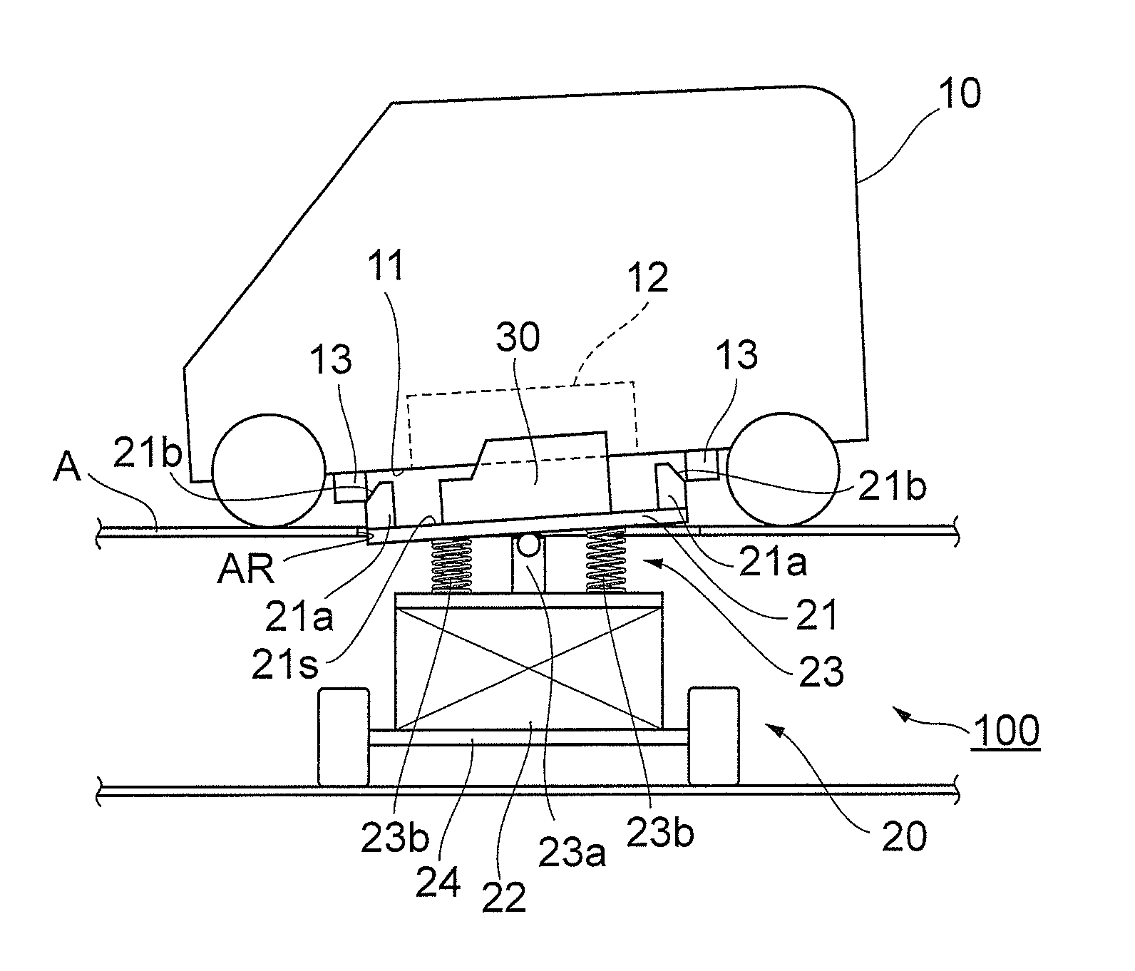
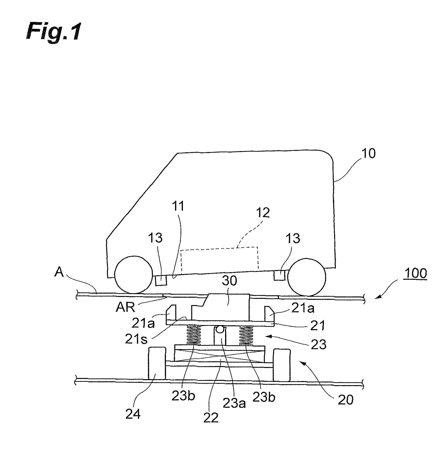
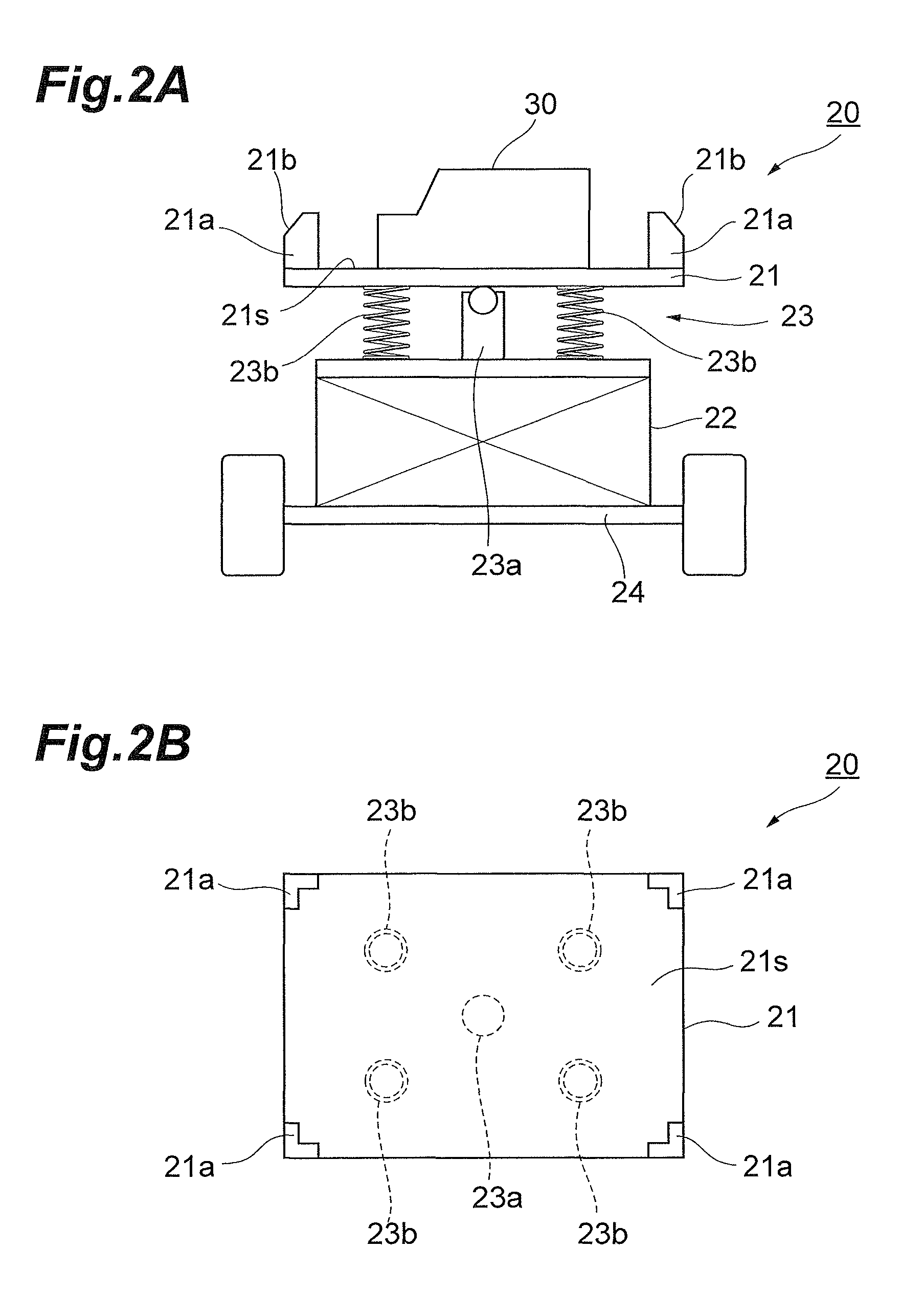
[0019]FIG. 1 is a schematic side view illustrating an embodiment of the battery unit mounting structure in accordance with one aspect of the present invention. The battery unit mounting structure 100 illustrated in FIG. 1 is equipped with a battery transfer apparatus (battery unit mounting apparatus) 20 to be placed under a horizontal bench A carrying an electric vehicle (vehicle) 10. Through an aperture AR of the bench A, the battery transfer apparatus 20 mounts a battery unit 30 to the electric vehicle 10 carried on the bench A from a b...


PUM


Abstract

A battery unit mounting apparatus for mounting a battery unit to a vehicle from a bottom face side of the vehicle comprises a table having a mount surface for mounting the battery unit, a lift for moving the table up and down with respect to the bottom face of the vehicle, and a connection mechanism for connecting the table and the lift to each other. The connection mechanism connects the table and the lift to each other such that the battery unit or table comes into contact with the bottom face of the vehicle so as to tilt the mount surface by a predetermined inclination with respect to the bottom face of the vehicle.

Description

BACKGROUND OF THE INVENTION[0001]1. Field of the Invention[0002]One aspect of the present invention relates to a battery unit mounting apparatus and battery unit mounting structure for mounting a battery unit to a vehicle from its bottom face side.[0003]2. Related Background Art[0004]Japanese Patent Application Laid-Open No. 2010-173364 (hereinafter referred to as “Patent Literature 1”) discloses a battery mounting apparatus aimed at making a battery attachable and detachable regardless of the inclination of a vehicle body. For achieving the aim in the battery mounting apparatus disclosed in Patent Literature 1, the state of inclination of a polyhedral jig having a plurality of fixing jigs for fixing a battery is adjusted beforehand according to the inclination of the vehicle body. More specifically in the battery mounting apparatus, a position detection sensor detects the inclination in a pitch direction of a vehicle body floor, and the amount of rotation of a rotary actuator about...

Claims


Application Information

Patent Timeline
Patent Type & Authority Patents(United States)
IPC IPC(8): B60R16/04B60K1/04
CPCB60K1/04B60K2001/0472Y02T90/12
Inventor OHGITANI, IKKEIFUKAGAWA, TAKAHIROOJIMA, YOSHIOMOTOYA, AKIHIKOMAKI, HIDEYUKI
Owner TOYOTA IND CORP
Why Eureka
Try Eureka