Optical element for measuring information of living body and device for measuring information of living body using the optical element

a technology of optical elements and living bodies, applied in the direction of instruments, diagnostic recording/measuring, applications, etc., to achieve the effects of reducing the degree of contact, high precision, stability and ease, and reducing the effect of insufficient conta

Inactive Publication Date: 2006-08-17
PANASONIC CORP
View PDF13 Cites 10 Cited by
  • Summary
  • Abstract
  • Description
  • Claims
  • Application Information

AI Technical Summary

Benefits of technology

[0032] Based on the above structure, even though the degree of the contact between the tissue of living body and the above groove is declined when the bottom of the valley part of the groove became small in size to prevent the tissue of living body to go into the above valley part, and when the tissue of living body is deformed at the peak part in between the grooves, a light can be applied only to a part where the degree of the contact is high, and the light from the part with high degree of contact can be securely emitted. Therefore, by using the optical element of the present invention, a body fluid component in a test sample such as a living body can be measured noninvasively with high precision, stability, and ease.
[0033] Thus, according to the present invention, in an apparatus for measuring information of living body including an optical element having a groove, the effects of the insufficiency in the degree of contact can be alleviated and a concentration of a target component in a test sample can be measured with stability and ease.

Problems solved by technology

However, the conventional optical measurement method and optical measurement device such as the above had the following problems.

Method used


Image

  • Optical element for measuring information of living body and device for measuring information of living body using the optical element
  • Optical element for measuring information of living body and device for measuring information of living body using the optical element
  • Optical element for measuring information of living body and device for measuring information of living body using the optical element

Examples


embodiment 1

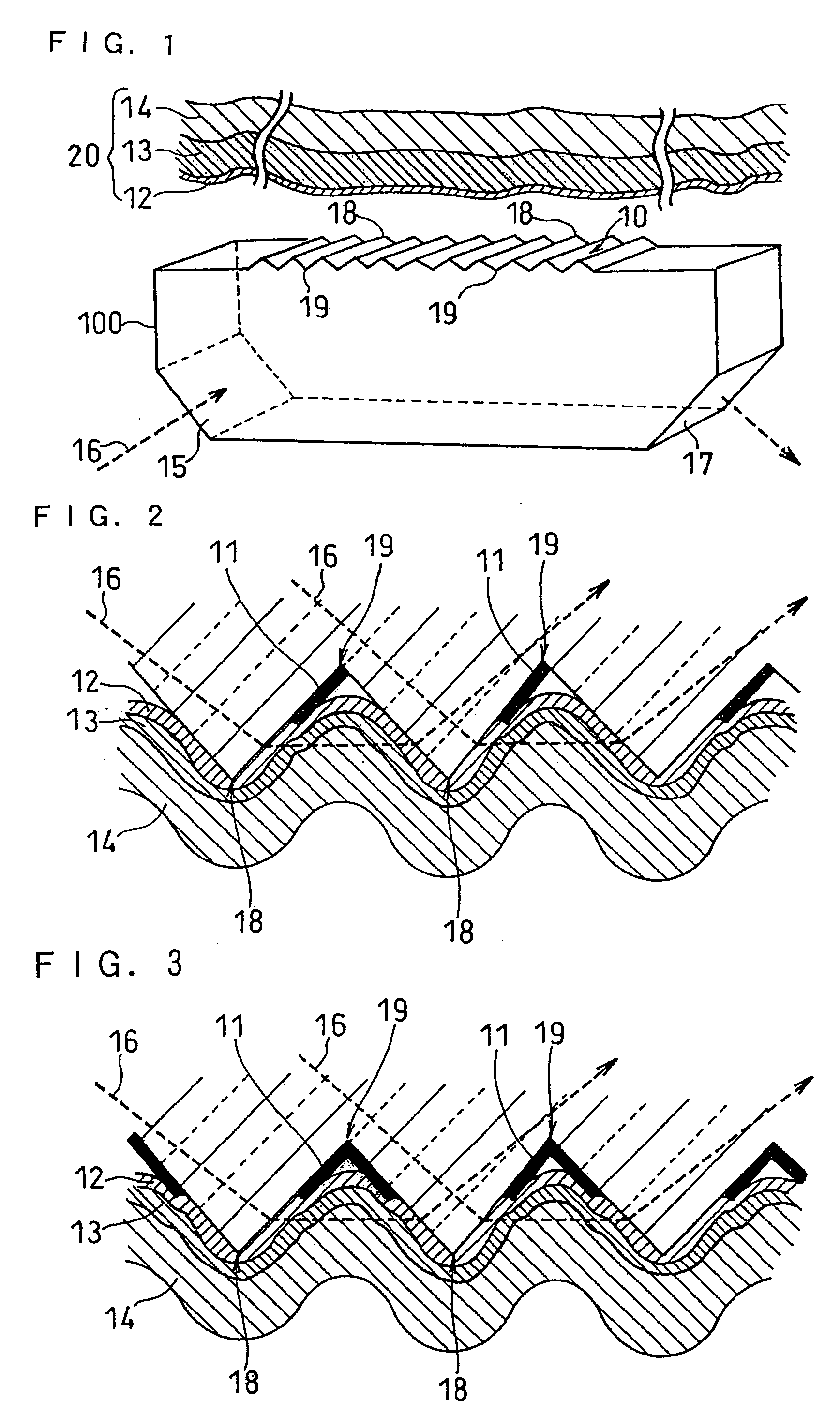
[0045]FIG. 1 is a perspective view illustrating an optical element for measuring information of living body in an embodiment of the present invention. Also, FIG. 2 is a cross sectional, enlarged, upside-down view of a part where the groove 10 and the living body 20 are making contact. As shown in FIG. 1, an optical element 100 for measuring information of living body of this embodiment has a groove 10.

[0046] In the groove 10, a part where the living body 20 makes the first contact is a peak part 18, and the bottom of the groove 10 is a valley part 19, viewing the optical element 100 for measuring information of living body from the side.

[0047] In this embodiment, wavelength of the light to be measured is to be a light in the range of mid-infrared light not less than 2.5 μm. A light 16 is applied from a light incident surface 15. The light 16 applied is emitted from the optical element 100 for measuring information of living body once at the groove 10, as shown in FIG. 2.

[0048] Th...

embodiment 2

[0061] The wavelength of the light for the measurement in this embodiment is to be a light in near-infrared range below 2.5 μm. In this embodiment, the size of groove 10 and the length of the light transmittance controlling means 11 (that is, the length of the part where a light transmittance controlling means 11 is formed) are different, compared with the Embodiment 1.

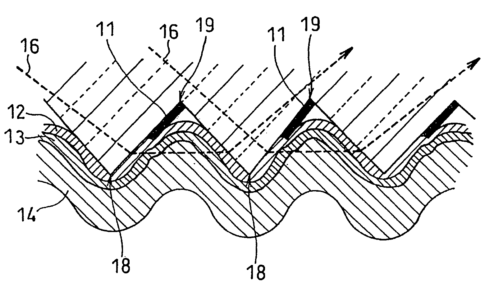
[0062] When the measurement wavelength is in the near-infrared range, the distance which the light can pass through in the living body is approximately 2 mm. Therefore, it is preferable that the width of an opening of the groove 10 is set to become approximately 2 mm. At this time, in a valley part 19 of the groove 10, it is preferable that a light transmittance controlling means 11 of at least 100 μm is formed from the bottom part of the valley part 19 of the groove 10, along the wall surface of a light incident surface side of each groove 10, as shown in FIG. 2.

[0063] Also, it is preferable that the light transmit...

embodiment 3

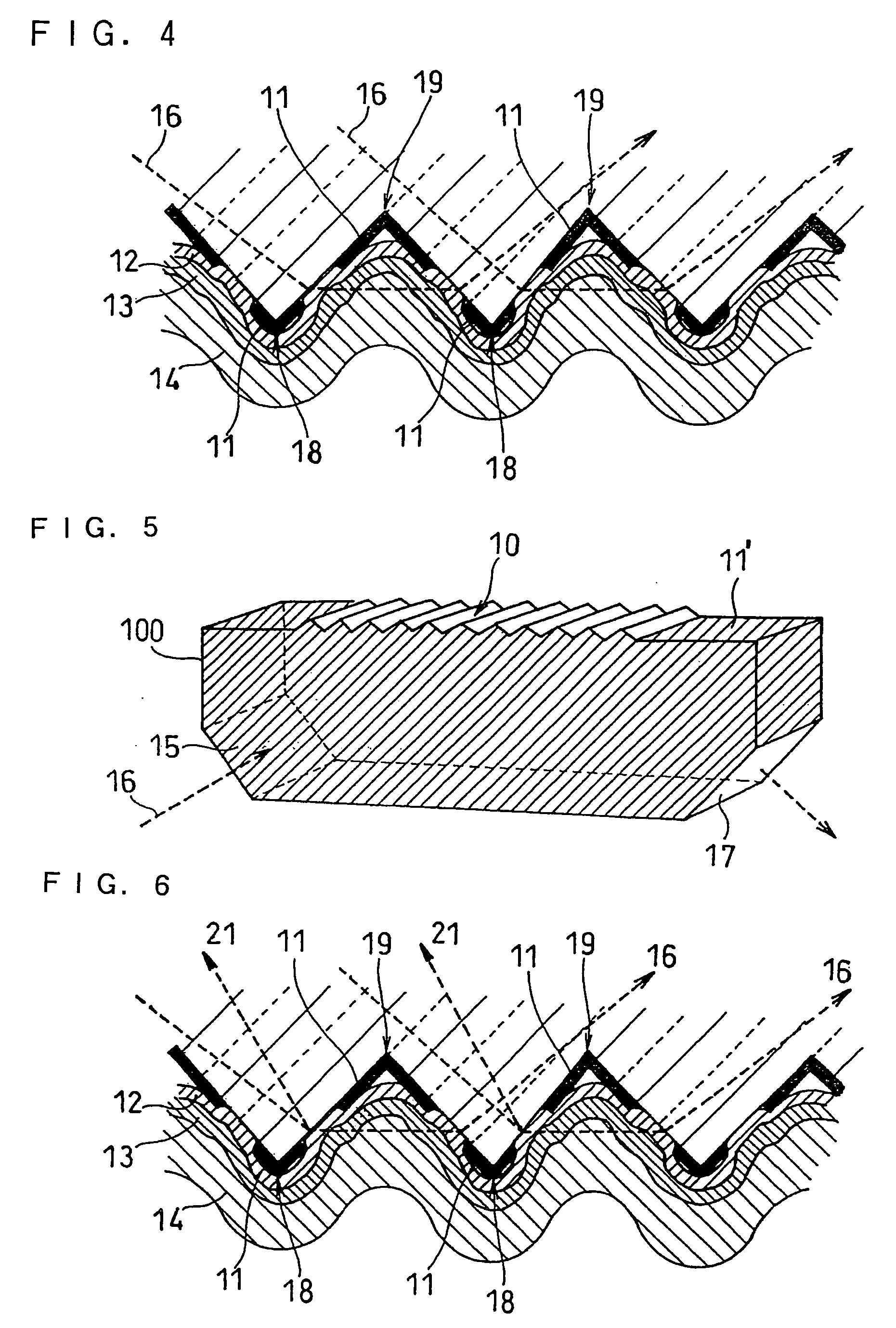
[0069]FIG. 5 is a perspective view illustrating a structure of an optical element for measuring information of living body in another embodiment of the present invention. An optical element 100 for measuring information of living body shown in FIG. 5 has a light transmittance controlling means 11′ on a part except for a groove 10, a light incident surface 15, and a light emission surface 17. That is, as shown with the hatch pattern portions in FIG. 5, the light transmittance controlling means 11′ is provided at an entire surface of the optical element 100 for measuring information of living body except for the groove 10, the light incident surface 15 and the light emission surface 17.

[0070] In the groove 10, the light transmittance controlling means 11 is provided as in any of the case shown in FIGS. 2 to 4.

[0071] When the light 16 is entered in the groove 10, there exist a transmitted light which is emitted from the groove 10 and from the optical element 100 for measuring informa...


PUM

PropertyMeasurementUnit
incident angleaaaaaaaaaa
wave lengthaaaaaaaaaa
wavelengthaaaaaaaaaa

Abstract

The present invention provides an optical element for measuring information of living body for noninvasively measuring a body fluid component in a test sample of living body with high accuracy, stability, and ease. The optical element includes a light incident surface, a contact surface contacting living body and having a groove to protrude living body and a light emission surface, in which a light incident from the light incident surface is applied to living body, and the light absorbed and scattered by living body is received and emitted from the light emission surface, a light transmittance controlling means is formed from the bottom part of the valley part of the groove, on at least a part of a wall surface of the light incident surface side and/or on a wall surface of the light emission surface side of the groove.

Description

TECHNICAL FIELD [0001] The present invention relates to an optical element used for optically measuring tissue of a living body to noninvasively measure a living body component such as glucose, cholesterol, urea, or triglyceride in a body fluid, and to an apparatus for measuring information of a living body using the optical element. BACKGROUND ART [0002] Conventionally, there have been proposed various methods in which a specific component in a living body or in a solution are measured by using an optical measuring device. For example, there has been known a method in which a blood-sugar level is measured by bringing upper and lower lips into intimate contact with a transparent attenuated total reflectance (ATR) element having a pair of reflecting surfaces facing in parallel. [0003] In this method, an ATR element which is an ATR prism comprising zinc selenide, silicon, or germanium is held in a mouth, and a light is applied to the ATR element while the ATR element is pressed by the...

Claims


Application Information

Patent Timeline
Patent Type & Authority Applications(United States)
IPC IPC(8): A61B5/00A61B5/145A61B5/1455G01N21/01G01N21/27G01N21/31G01N21/35G01N21/85
CPCA61B5/14532A61B5/14546A61B5/1455A61B2562/146G01N21/01G01N21/31G01N21/8507G01N2021/8535G01N2201/064
Inventor SHIOI, MASAHIKO
Owner PANASONIC CORP
Why Eureka
Try Eureka