Method, apparatus, and computer program product in a processor for performing in-memory tracing using existing communication paths

a technology of in-memory tracing and processor, applied in the field of data processing systems, can solve the problems of inability to collect characterization data from them, the initial system architecture draft is not easy to grow, and the tradeoffs in the design of commercial server systems are never simpl

Inactive Publication Date: 2006-08-17
IBM CORP
View PDF8 Cites 23 Cited by
  • Summary
  • Abstract
  • Description
  • Claims
  • Application Information

AI Technical Summary

Problems solved by technology

Making tradeoffs in the design of commercial server systems has never been simple.
For large commercial systems, it may take years to grow the initial system architecture draft into the system that is ultimately shipped to the customer.
Servers in general and commercial servers in particular place a large demand on system and operator resources, so the opportunities to collect characterization data from them are limited.
As computer systems migrate towards the use of sophisticated multi-stage pipelines and large SMP with SMT based systems, the ability to debug, analyze, and verify the actual hardware becomes increasingly more difficult, during development, test, and during normal operations.
There are problems with the prior art method.
This is a significant limitation, particularly in systems that have only one memory controller.
In addition to the limitations described above, the prior art requires that the system be booted to a trace mode instead to a normal mode when tracing is desired.
The size of the dedicated memory will not be able to be changed without rebooting the system and executing another IPL process.

Method used


Image

  • Method, apparatus, and computer program product in a processor for performing in-memory tracing using existing communication paths
  • Method, apparatus, and computer program product in a processor for performing in-memory tracing using existing communication paths
  • Method, apparatus, and computer program product in a processor for performing in-memory tracing using existing communication paths

Examples


Embodiment Construction

[0041] A preferred embodiment of the present invention and its advantages are better understood by referring to the figures, like numerals being used for like and corresponding parts of the accompanying figures.

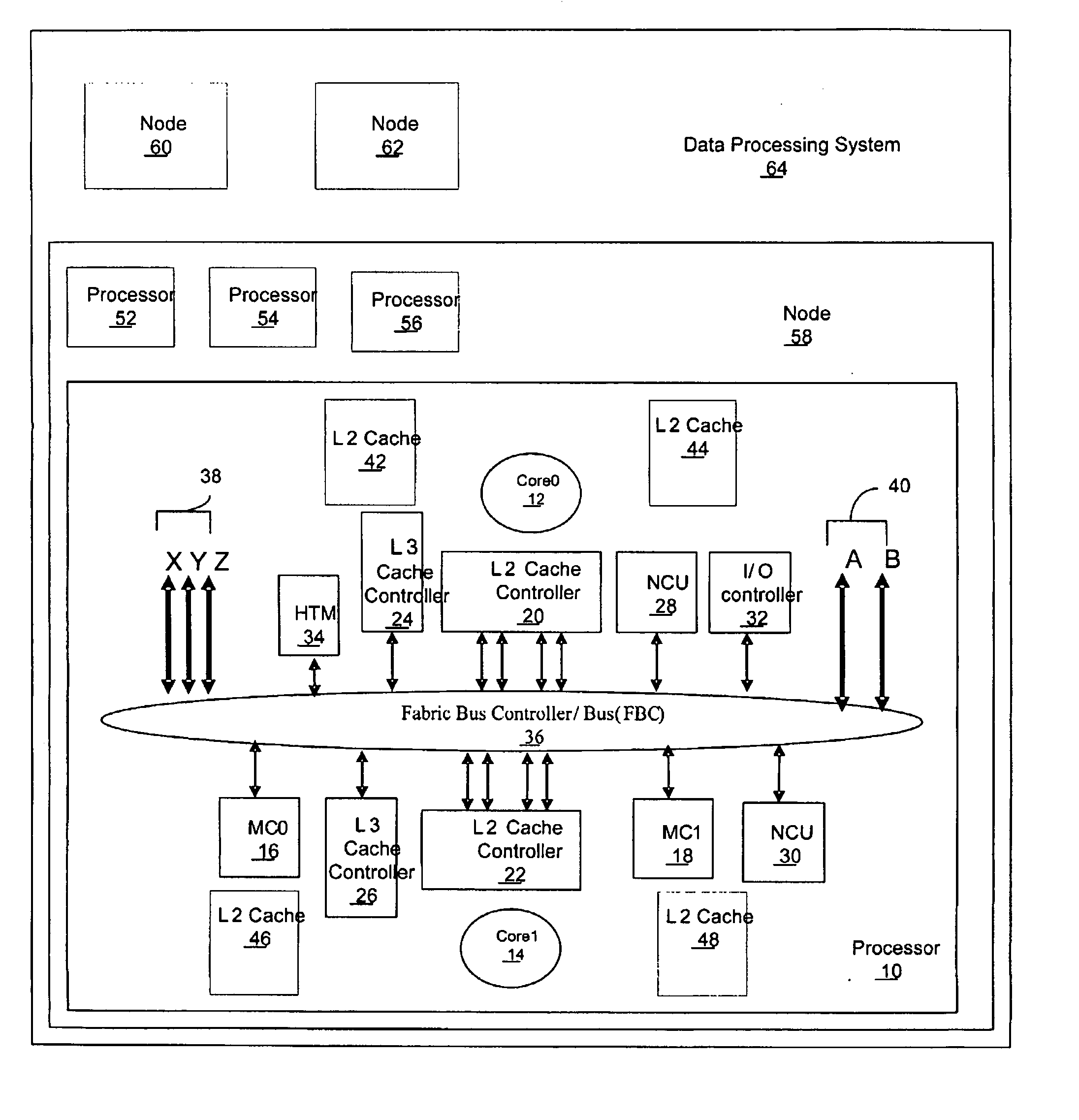
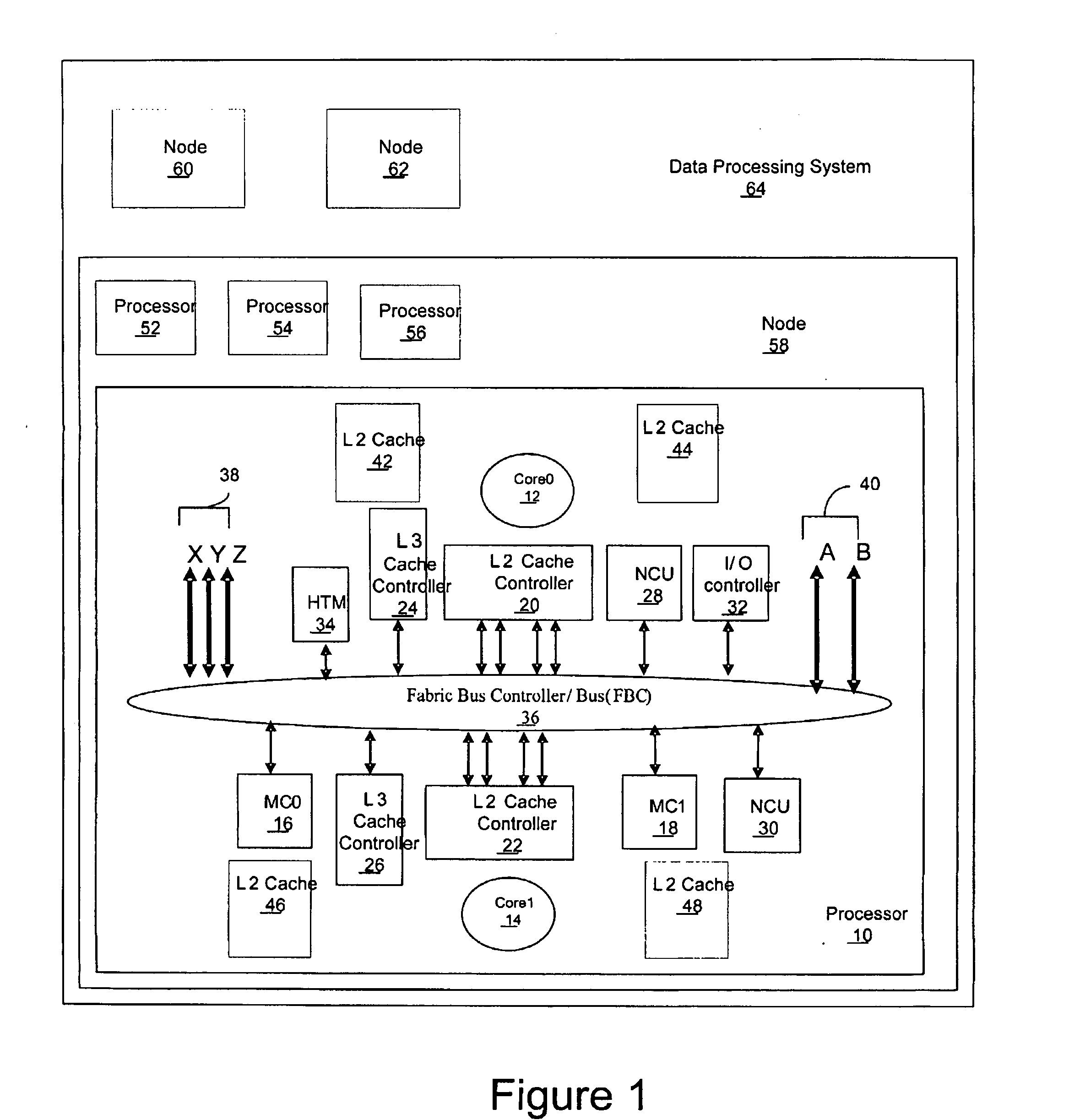
[0042] The present invention is a method, apparatus, and computer program product for performing in-memory hardware tracing using an existing system bus. A hardware trace facility is provided as one of the processing units included in a processor. The hardware trace facility is referred to herein as a hardware trace macro (HTM).

[0043] The HTM looks like any other processing unit in the processor to the fabric. It uses the same data and addressing scheme, protocols, and coherency used by the other processing units in the processor. Therefore, there is no need for extra wiring or side band signals. There is no need for a special environment for verification since it will be verified with the standard existing verification functions.

[0044] The HTM captures hardware trace data...


PUM


Abstract

A method, apparatus, and computer program product are disclosed for performing in-memory hardware tracing in a processor using an existing system bus. The processor includes multiple processing units that are coupled together utilizing the system bus. The processing units include a memory controller that controls a system memory. Information is transmitted among the processing units utilizing the system bus. The information is formatted according to a standard system bus protocol. Hardware trace data is captured utilizing a hardware trace facility that is coupled directly to the system bus. The system bus is utilized for transmitting the hardware trace data to the memory controller for storage in the system memory. The memory controller is coupled directly to the system bus. The hardware trace data is formatted according to the standard system bus protocol for transmission via the system bus.

Description

CROSS-REFERENCE TO RELATED APPLICATIONS [0001] The subject matter of the present application is related to copending U.S. applications, Ser. No. ______ [docket AUS920040993US1], titled “Method, Apparatus, and Computer Program Product in a Processor for Concurrently Sharing a Memory Controller Among a Tracing Process and Non-Tracing Processes Using a Programmable Variable Number of Shared Memory Write Buffers”, Ser. No. ______ [docket AUS920040994US1], titled “Method, Apparatus, and Computer Program Product in a Processor for Dynamically During Runtime Allocating Memory for In-Memory Hardware Tracing”, Ser. No. ______ [docket AUS920041000US1], titled “Method, Apparatus, and Computer Program Product for Synchronizing Triggering of Multiple Hardware Trace Facilities Using an Existing System Bus”, and Ser. No. ______ [docket AUS920041001US1], titled “Method, Apparatus, and Computer Program Product in a Processor for Balancing Hardware Trace Collection Among Different Hardware Trace Faci...

Claims


Application Information

Patent Timeline
Patent Type & Authority Applications(United States)
IPC IPC(8): G06F11/00
CPCG06F11/2268G06F11/348
Inventor AL-OMARI, RA'ED MOHAMMADMERICAS, ALEXANDER ERIKSTARKE, WILLIAM JOHN
Owner IBM CORP
Why Eureka
Try Eureka